10-ENGLISH
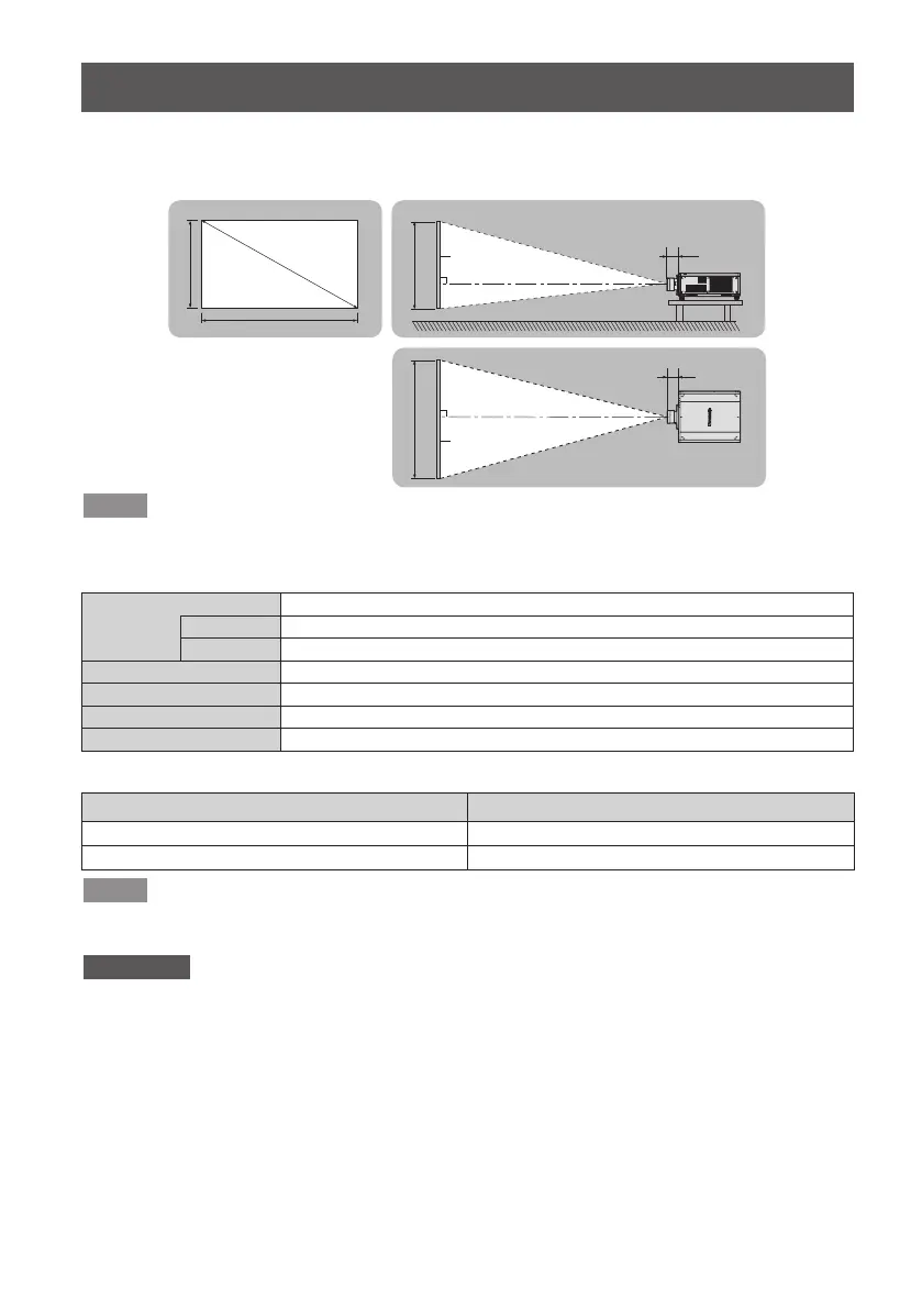
Projection relationships
The dimensional relationship between the screen and the projector is shown below.
■
Dimensional relationship diagram
Note
z
This diagram assumes that the size and position of the projected image will be adjusted so
that the image lls the entire screen.
z
This illustration is not drawn to scale.
L Projection distance
LW Minimum distance
LT Maximum distance
L1 Lens protrusion dimension
SH Projected image height
SW Projected image width
SD Projected image size
z
Dimension for L1 (approximate values)
(Unit: m)
Projector model
Dimension for L1 (approximate value)
PT-RQ32K / PT-RZ31K / PT-RS30K 0.18
PT-RZ21K / PT-RS20K 0.21
Note
z
The illustrations of projectors in this manual are for informational purposes only and do not
represent a specic projector model. Congurations may vary with the model.
Attention
z
To prevent obstruction of the intake and exhaust vents, install the projector with a
clearance at least 500 mm (1 ft. 7 in.) from walls and objects.
If you are installing the projector in a sealed space, be sure to provide additional air
conditioning equipment and ventilation equipment. Insufcient ventilation will result in an
accumulation of heat and may activate the projector's protection circuit.
z
Avoid setting up in places which are subject to sudden temperature changes, such as near
an air conditioner or lighting equipment (studio lamps, etc.).
■
Dimensional relationship
For details on the projection distance (L), refer to “Projected image size and Projection
distance” and “Projection distance formulas” in the Appendix.
SD
L (LW/LT)
L1
L1
L (LW/LT)
SW SH
SH
SW
投写画面
スクリーン
スクリーン
Projected image
Screen
Screen
 Loading...