5
Use signal switch for manual control of High/Low CFM modes
On to use Pick-A-Flow setting ( High CFM )
Do not connect the red signal wires to a live power
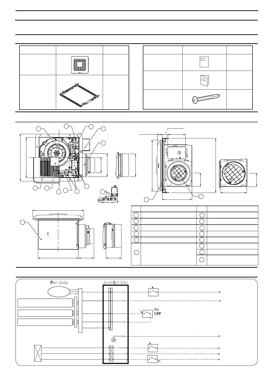
DIMENSIONS
WIRING DIAGRAM
Multi-Speed module (FV-0511VKSL2
only, other models not included)
Plug ‘N Play module slot
Plug ‘N Play module slot
Power switch
Power switch
Signal switch
Fan body
DC-Motor
Junction box
SUPPLIED ACCESSORIES
1
1
1
Installation
instructions
Self-drilling
screw
Warranty
sheet
Part name Part nameAppearance Quantity
Grille
4
TM
Flex-Z Fast
bracket
(with 4
tapping screws
-ST4.2X20)
1
Appearance Quantity
UNPACKING
Unpack and carefully remove the unit from packing.
Refer to the Supplied Accessories list to verify that all parts are present.
Unit: inches (mm)
FV-1115VKL2
FV-0511VKSL2
FV-1115VKL2
10 1/4 (260)
5 7/8 (151)
5 7/8 (148)
13 (330)
7 1/2 (190)
1 1/4 (30)
4 1/2 (114)
1 1/2 (37)
3 7/8 (100)
12 (304)
3 3/8
(86)
13 1/4 ~ 15 1/2 (336~394)
16 1/2 ~ 18 3/4 (419~480)
21 1/4 ~ 23 1/2 (540~597)
3 3/8
(86)
6 5/8 (169)
10 1/4 (261)
13 (330)
3 7/8
(100)
3 7/8
(100)
1
8
3
4
5
2
FV-0511VKL2
FV-1115VKL2
Part name
Blade
Grille
Part name
No. No.
82
4
1
3
5
6
10
12
11
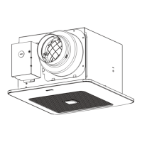
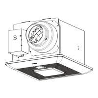
Motion sensor location
(FV-MSVK1 not included)
Multi-Speed module
(FV-0511VKSL2 only,
other models not included)
Connector cover
Base PCB box
Pick-A-Flow switch
Fan body
Damper
TM
Flex-Z Fast bracket
Junction box
9
7
6
Adaptor
Lightingunit
14
7
9
7
10
11
12
14
Main PCB box
13
13
supply (AC 120V 60 Hz), it will damage the product.
Please use an optional switch to connect the red
signal wires.
English
Blue
White
Black
Black
White
Red
Red
Live
(
N.Light
)*
Green
LED
AC120V
60Hz
(Power supply)
Earth ground
Live (Fan)
Neutral
Live (Light)
Neutral
Power switch
AC120V
60Hz
(Power supply)
Night light
*
Green
OFF to use multi-speed module setting ( Low CFM )
 Loading...