15
ERROR INDICATION
● In case of errors, attempt the following measures.
Error
indication
Description Remedy
EEPROM is broken or reached the end of its
working life.
Please contact our ofce.
EEPROM writing error
Load of the sensing output is short-circuited
causing an over-current to ow.
Turn OFF the power and check the load.
Communication error when the ampliers are
mounted in cascade.
Verify that there is no loose or clearance between
ampliers.
Communication error between the upper com-
munication unit and ampliers.
Verify that there is no loose or clearance between
the upper communication unit and ampliers.
16
SPECIFICATIONS
Type
Series connection type
NPN output PNP output
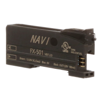
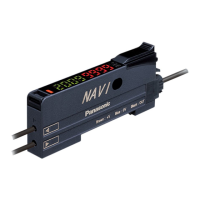
Model No.
FX-501 FX-501P
Supply voltage 12 to 24V DC % Ripple P-P10% or less
Power consumption
(Note 1)
Normal operation: 960mW or less (current consumption 40mA or less at 24V supply voltage)
Eco mode: 680mW or less (current consumption 28mA or less at 24V supply voltage)
Sensing output
NPN open-collector transistor
• Maximum sink current: 100mA (Note 1)
• Applied voltage: 30V DC or less
(Between sensing output and 0V)
• Residual voltage: 2V or less (Note 2)
[At 100m
A (Note 1)
sink current]
PNP open-collector transistor
• Maximum source current: 100mA (Note 1)
• Applied voltage: 30V DC or less
(Between sensing output and +V
)
• Residual voltage: 2V or less (Note 2)
[At 100m
A (Note 1)
source
current]
Output operation Switchable either Light-ON or Dark-ON
Short-circuit protection
Incorporated
Response time
H-SP: 25μs or less, FAST: 60μs or less, STD: 250μs or less, LONG: 2ms or less,
U-LG: 4ms or less, HYPR: 24ms or less, Selectable
Protection IP40 (IEC)
Ambient temperature
-10 to +55°C (If 4 to 7 units are mounted in cascade: -10 to +50°C or if 8 to 16 units are
mounted in cascade: -10 to +45°C) (No dew condensation or icing allowed)
Storage: -20 to +70°C
Ambient humidity 35 to 85% RH, Storage: 35 to 85% RH
Material Enclosure: Polycarbonate, Key: Polyacetal, Protective cover: Polycarbonate
Weight (Main body only)
Approx. 15g
Accessory
FX-MB1
(Amplier protection seal): 1 set.
Notes: 1) 50mA max. if 5 or more series connection types are connected together.
2) In case of using the quick-connection cable (cable length 5m) (optional).
3) Cables are not accessories. Be sure to use cables in table below.
<Series connection type>
Cable
Cable length 1m Cable length 2m Cable length 5m
Main cable Sub cable Main cable Sub cable Main cable Sub cable
FX-501□ CN-73-C1 CN-71-C1 CN-73-C2 CN-71-C2 CN-73-C5 CN-71-C5
17
CAUTIONS
● This product has been developed / produced for industrial use only.
● Make sure that the power supply is OFF while adding or removing the ampliers.
● Take care that if a voltage exceeding the rated range is applied, or if an AC
power supply is directly connected, the product may get burnt or be damaged.
● Take care that short-circuit of the load or wrong wiring may burn or damage
the product.
● Do not run the wires together with high-voltage lines or power lines, or put
them in the same raceway.
This can cause malfunction due to induction.
● The specication may not be satised in a strong magnetic eld.
● Verify that the supply voltage variation is within the rating.
● If power is supplied from a commercial switching regulator, ensure that the
frame ground (F.G.) terminal of the power supply is connected to an actual
ground.
● In case noise generating equipment (switching regulator, inverter motor, etc.)
is used in the vicinity of this product, connect the frame ground (F.G.) terminal
of the equipment to an actual ground.
● The ultra long distance (U-LG, HYPR) mode is more likely to be affected by
extraneous noise since the sensitivity of that is higher than the other modes.
Make sure to check the environment before use.
● Do not use during the initial transient time (H-SP, FAST, STD: 0.5 sec., LONG,
U-LG, HYPR: 1 sec.) after the power supply is switched ON.
● Be sure to using the quick connection cable (optional) as cable. When you ex-
tend the cable, be sure to use cables which have 0.3mm
2
or more of conductor
cross-section area. Extension up to total 100m is possible. However, in order
to reduce noise, make the wiring as short as possible.
● Make sure that stress by forcible bend or pulling is not applied to the sensor
cable joint and ber cable.
● This product is suitable for indoor use only.
● Avoid dust, dirt, and steam.
● Take care that the product does not come in contact with oil, grease, organic
solvents such as thinner, etc., strong acid or alkaline.
● This product cannot be used in an environment containing inammable or ex-
plosive gasses.
● Never disassemble or modify the product.
● This product adopts EEPROM. Settings cannot be done 100 thousand times
or more because of the EEPROM’s lifetime.
13
OPTICAL COMMUNICATION
● When the setting of data bank loading / saving, copy setting, or copy action
setting is conducted via optical communications, cascade the sub ampliers
right side to the main amplier as follows.
However, in case using data bank loading / saving, use
FX-502
□ or
FX-505
□
-C2
as main amplier.
● If an amplier is under any of the following conditions, the setting of data bank
loading / saving, or copy setting cannot be carried out.
• Copy lock setting is set to copy lock ON “ .”
• Digital display is blinking
• External input setting of main amplier is set to
“ .
” (Only data-
bank loading / saving)
● When communication protocol of a
sub amplifier is set to communication
emission halt “ ” the setting
of data bank loading / saving, or copy
setting cannot be carried out to sub
ampliers subsequent to the mentioned
amplier.
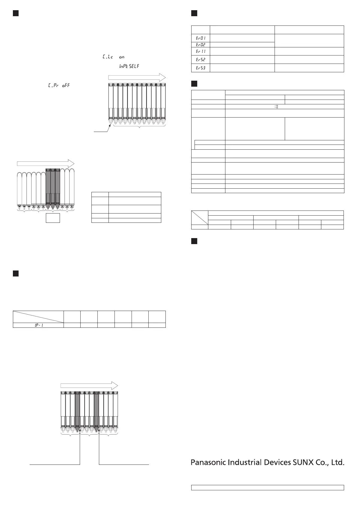
● Make sure to mount closely like follows
since interference prevention function is
conducted by optical communication.
Main
amplier
Sub ampliers
Communication direction
● When this product and other products (e.g. ber sensor ampliers, pressure
sensor controllers, etc.) are connected together in cascade, install those prod-
ucts so that they are in order of Group A, B, D and C as shown in the right g-
ure. This product is included in Group D.
Group
A
Group
B
Group
D
Group
C
Communication direction
Group Model No.
A
FX-301□ (Conventional version unit)
FX-301B□/G□/H□, LS-401□
B
FX-301□ (Modied version unit)
FX-305□, FX-301□-C1
C LS-403□, DPS series
D FX-500 series
● As for the products that are located between different groups, afx the ampli-
er protection seal
FX-MB1
(optional) on the communication window of each
corresponding product.
● Within each group, identical models should be connected in a lump.
● In case conducting copy setting of this device and other
FX-500
series togeth-
er, functions which are incorporated in this device will be copied but functions
which are not incorporated in this device will not be copied.
14
INTERFERENCE PREVENTION FUNCTION
● This device incorporates an interference prevention function by setting different emit-
ting frequencies from an interference prevention function by optical communication.
● For Interference prevention function setting procedure, refer to
<PRO5>
in
“
PRO MODE OPERATION MANUAL
.”
● Possible number of ampliers for interference prevention function is different
as shown in table below.
Response time
Interference
prevention function setting
H-SP FAST STD LONG U-LG HYPR
0 2 4 8 8 12
● In case putting in more ampliers than limit of interference prevention function,
put the amplier protection seal to amplier which is adjacent of end of an ampli-
er that the interference function is valid or set OFF in communication protocol
setting of the end of amplier that the interference prevention function is valid.
Example: Putting in 12 of this device and set STD of response time setting.
• Possible number of interference prevention is 4.
Put the amplier protection seals 4th and 5th ampliers and between 8th
and 9th ampliers or change the communication protocol setting of 4th and
8th to OFF since interference prevention works from 1st to 4th, from 5th to
8th and 9th to 12th.
Communication direction
Interference
prevention
possible
range
Put a protection seal between
4th and 5th amplier.
Or set communication protocol
setting in 4th to OFF.
Put a protection seal between
8th and 9th amplier.
Or set communication protocol
setting in 8th to OFF.
Interference prevention
possible range
Interference prevention
possible range
● In case mounting more ampliers whose response time setting are different,
put protection seal between ampliers that have different response time setting
or set communication protocol setting of the upper amplier to OFF.
● For communication protocol setting procedure, refer to
<PRO4>
in “
PRO
MODE OPERATION MANUAL
.”
http://panasonic.net/id/pidsx/global
Overseas Sales Division (Head Ofce)
2431-1 Ushiyama-cho, Kasugai-shi, Aichi, 486-0901, Japan
Phone: +81-568-33-7861 FAX: +81-568-33-8591
For sales network, please visit our website.
PRINTED IN CHINA © Panasonic Industrial Devices SUNX Co., Ltd. 2015
 Loading...