e the troubleshooting procedures very carefully. It may have a serious problem.
The symptom: No response when the power is turned on.
, and keys are not accepted.)
The first step is to check the power source. If there is no problem with the power supply unit, the problem may lie in the digital
As there are many potential causes in this case (ASIC
, DRAM, etc.), it may be difficult to specify what you should chec
a mistake is made in the order
of checks, a normal part may be determined faulty, wasting both time and money
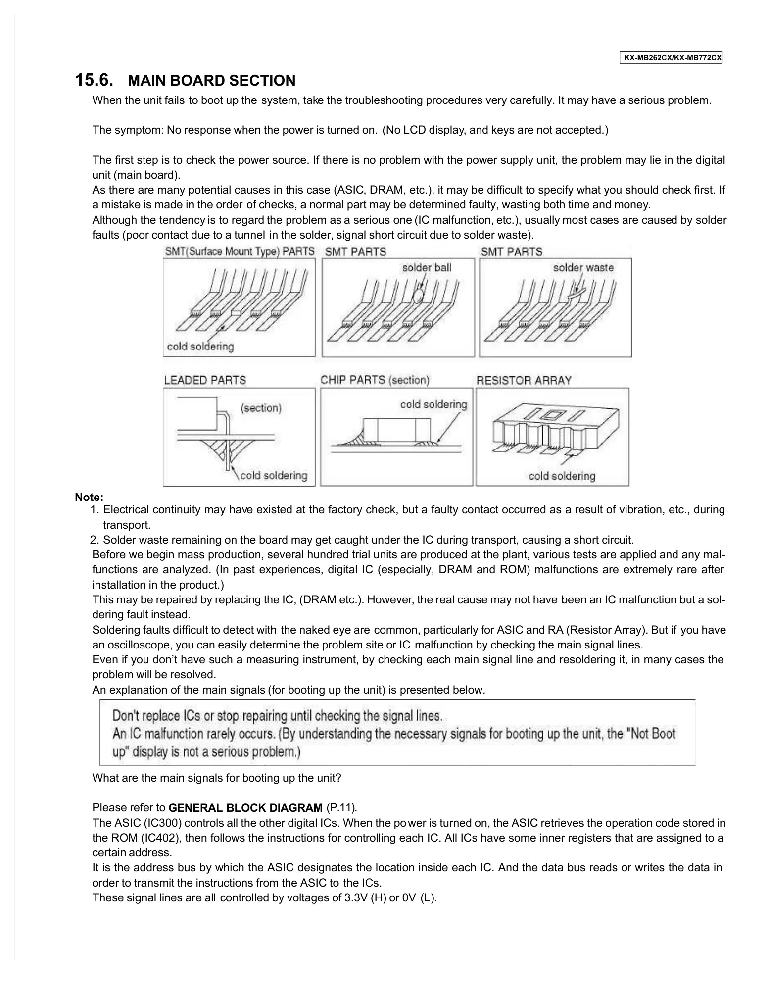
faults (poor contact due to a tunnel
in the solder, signal short circuit due to solder waste).
Electrical continuity may hav
e existed at the factory check, but a faulty contact occurred as a result of vibration, etc., during
Solder waste remaining on the board may get caught under the IC during transport, causing a short circ
Before we begin mass production, several hundred trial units are produced at the plant, various tests are applied and any mal-
functions are analyzed. (In past experiences, digital IC (especially, DRAM and ROM) malfunctions are extremely rare after
installation in the product.)
This may be repaired by replacing the IC, (DRAM etc.). However
, the real cause may not have
been an IC malfunction but a sol-
Soldering faults difficult to detect with
common, particularly for ASIC and RA (Resistor Array). But if
an oscilloscope, you can easily determine the problem site or IC
malfunction by checking the main signal lines.
Even if you don’t have such a measuring instrument, by checking each main signal line and resoldering it, in many cases the
problem will be resolved.
An explanation of the main signals
(for booting up the unit) is pres
What are the main signals for booting up the unit?
The ASIC (IC300) controls all the other digital ICs. When the po
wer is turned on, the ASIC retrieves the operation code stored in
the ROM (IC402), then follows the instructions for controlling each IC. All ICs have some inner registers that are assigned to a
It is the address bus by which the ASIC designates the location inside each IC. And the data bus reads or writes the data in
order to transmit the instructions from the ASIC to
These signal lines are all
controlled by voltages of 3.3V (H) or 0V
 Loading...