Do you have a question about the Panasonic KX-TGF350N and is the answer not in the manual?
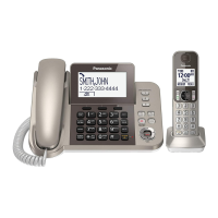
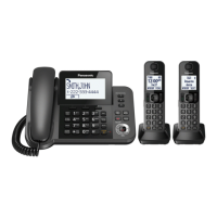
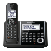
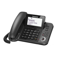
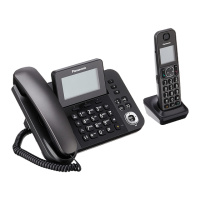
Details product features and variants like Champagne Gold and Metallic Black.
Specific safety instructions for experienced repair personnel.
Warns about the risks associated with improper battery replacement and disposal.
Provides information on lead-free solder usage and precautions.
Instructs on the proper procedure for discarding printed circuit boards.
Details the circuit architecture of the TGF35x/38x telephone series.
Describes the US-DECT system, including frame format and TDMA.
Illustrates the signal path within the radio components for reception and transmission.
Provides a block diagram of the main base unit's internal components and connections.
Details the circuit responsible for interfacing with the telephone line.
Shows the block diagram of the radio frequency section of the base unit.
Explains the operational principles of the base unit's systems.
Describes the power supply and reset functionalities of the base unit.
Details the circuit for handling telephone line connections and signals.
Explains circuits for detecting parallel connections and auto-disconnect features.
Describes how Caller ID and Call Waiting Caller ID information is processed.
Provides a block diagram of the handset's internal components.
Shows the block diagram of the radio frequency section of the handset.
Explains the operational principles of the handset's systems.
Describes the power supply and reset functionalities of the handset.
Details the circuit responsible for charging the handset's battery.
Explains how low battery conditions are detected and handled.
Describes the functionality of the speakerphone.
Explains the operational principles of the charger unit.
Provides instructions for accessing and operating the engineering mode.
Instructions for clearing user settings on the handset to factory defaults.
A step-by-step guide to diagnose and resolve issues.
Step-by-step instructions for disassembling the base unit, handset, and charger.
Detailed guide on replacing the LCD screen of the base unit.
Detailed guide on replacing the LCD screen of the handset.
Lists the necessary tools and equipment for measurements and adjustments.
Details how to connect and set up the JIG for testing and adjustments.
Instructions for connecting the JIG to the base unit.
Instructions for connecting the JIG to the handset.
Guide on installing necessary batch files onto a PC for device configuration.
Lists and explains the commands used for device testing and adjustment.
Specifies the standards and procedures for adjusting the base unit.
Specifies the standards and procedures for adjusting the handset.
Instructions for downloading programming and adjustment data after component replacement.
Step-by-step guide for replacing LLP package ICs.
Instructions on how to properly install an IC onto the PCB.
Detailed procedure for replacing flat package ICs.
Method for removing solder bridges from a PCB.
Terminal guide for components used in the base unit.
Terminal guide for components used in the handset.
General notes and safety notices regarding schematic diagrams.
Electrical schematic for the main base unit.
Electrical schematic for the handset.
Component view of the main base unit's printed circuit board.
Bottom view of the main base unit's printed circuit board.
Component view of the base unit's operation circuit board.
Component and bottom views of the base unit's hook switch circuit board.
Component view of the base unit's LCD circuit board.
Component view of the base unit's LED circuit board.
Component view of the handset's main printed circuit board.
Component view of the handset's BBIC module circuit board.
Lists cabinet and electrical parts for the base unit.
Lists cabinet and electrical parts for the handset.
Lists cabinet and electrical parts for the charger unit.
Details the accessories and packing materials included with each model.
Comprehensive list of all replaceable parts with part numbers and descriptions.
Replacement parts specifically for the base unit.
Replacement parts specifically for the handset.
Replacement parts specifically for the charger unit.
Lists all accessories and packing materials.
Lists the types and specifications of screws used.
Lists necessary fixtures and tools for repair and maintenance.
| Color | champagne gold |
|---|---|
| Speakerphone | yes |
| Expandable | yes |
| Paging Locator | yes |
| Volume Control | yes |
| Intercom | yes |
| Incoming Lines | 1 |
| Ringtones | 15 |
| Record Time | 17 minutes |
| Caller ID | yes |
| Call Waiting | yes |
| Answering System | yes |
| Flash Function | no |
| Conference Call | yes |
| Hold Button | yes |
| Caller ID Memory | 50 gigabytes |
| Phone Book Memory | 100 gigabytes |
| Handsets | no |
| Expansion Base Stations | 1 |
| Expansion Handsets | 0, 6 |
| Backlit Keypad | yes |
| Bluetooth | no |
| Frequency | dect 6.0 digital |
| Depth | 6.4 inches |
|---|---|
| Height | 4.1 inches |
| Net Weight | 20.5 ounces |