23
8.3. Disassembly Procedure
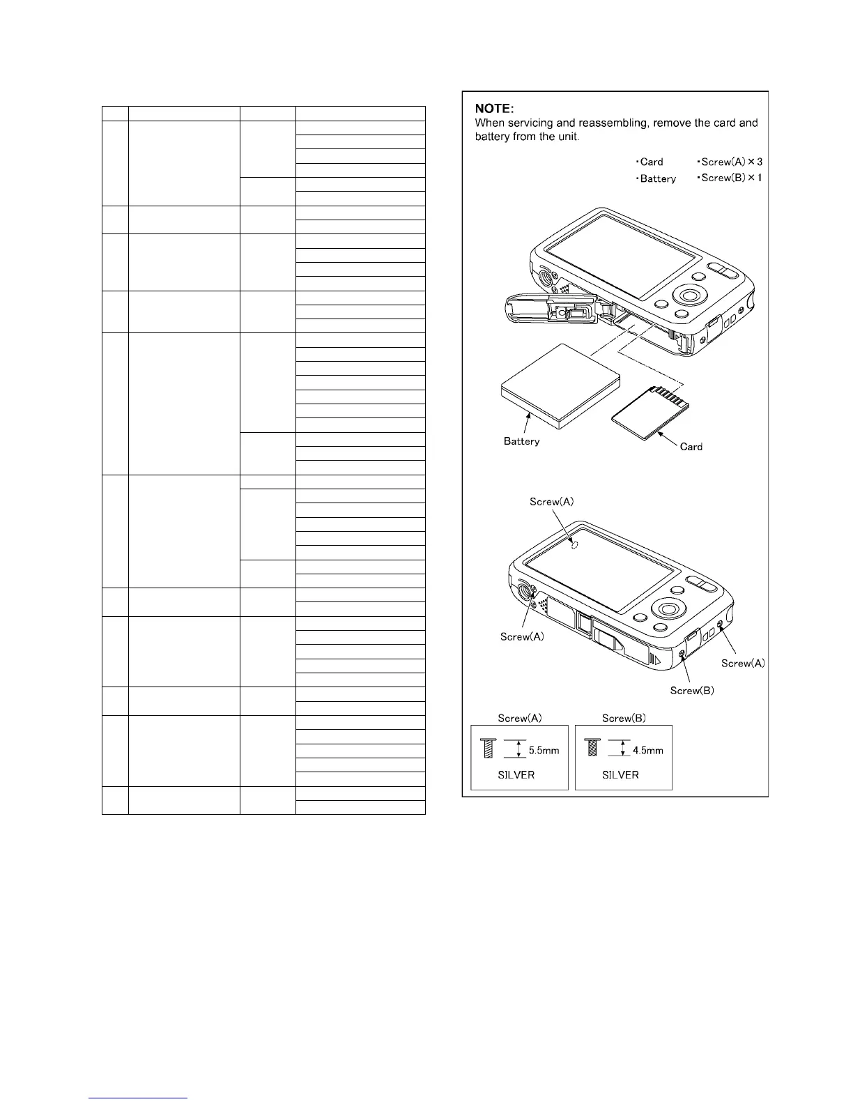
8.3.1. Removal of the Rear Case Unit
(Fig. D1)
No. Item Fig Removal
1 Rear Case Unit (Fig. D1) Card
Battery
3 Screws (A)
1 Screw (B)
(Fig. D2) 5 Locking tabs
Rear Case Unit
2 Center Ornament Unit (Fig. D3) 4 Locking tabs
Center Ornament Unit
3 Rear Operation Unit (Fig. D4) 1 Screw (C)
1 Convex
Connector (A)
Rear Operation Unit
4 LCD Unit (Fig. D5) 2 Locking tabs
Connector (B)
LCD Unit
5 Lens Unit (W/CCD) (Fig. D6) 1 Screw (D)
1 Screw (E)
3 Locking tabs
Frame Plate
Connector (C)
DPR Sheet A
Trigger Cover
(Fig. D7) Connector (D)
Connector (E)
Lens Unit (W/CCD)
6 Speaker
Flash P.C.B.
(Fig. D8) Discharge the E.Capacitor
(Fig. D9) FP8001 (Flex)
1 Screw (F)
Tripod Frame
Solder (2 points)
Speaker
(Fig. D10) Solder (3 points)
Flash P.C.B.
7 Front Case Unit (Fig. D11) 4 Locking tabs
Front Case Unit
8 Main P.C.B. (Fig. D12) Terminal Cover
1 Screw (G)
Solder (14 points)
1 Convex
Main P.C.B.
9 Flash Unit (Fig. D13) 2 Locking tabs
Flash Unit
10 Top P.C.B. (Fig. D14) 1 Screw (H)
Sheet
2 Convexes
1 Hooking part
Top P.C.B.
10 Battery Door Unit (Fig. D15) Battery Door Shaft
Battery Door Unit
 Loading...