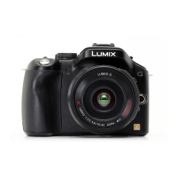
Do you have a question about the Panasonic Lumix DMC-S2P and is the answer not in the manual?
General guidelines for servicing the unit, emphasizing safety.
Procedure to check for leakage current when the unit is unplugged.
Procedure to check for leakage current when the unit is plugged in.
Instructions on safely discharging the capacitor on the flash PCB.
Techniques to prevent damage from static discharge to sensitive components.
Information on recycling lithium-ion batteries in the US.
Safety precautions for the AC power cord.
Procedure for replacing the unit's lithium battery.
Introduces the service manual's purpose and how to order parts.
Details on minimum replacement part sizes for main PCB and lens units.
Information on lead-free solder used in the equipment.
Guide to identifying model suffixes based on region/standards.
Functionality and display of error codes in the unit.
Lists and illustrates tools required for service.
Guidance on adjustment after replacing the main PCB.
A chart outlining the disassembly steps.
Diagrams showing the location of main PCBs.
Detailed steps for disassembling the unit.
Procedure for removing the rear case unit.
Procedure for removing the center ornament unit.
Procedure for removing the rear operation unit.
Procedure for removing the LCD unit.
Procedure for removing the lens unit including the CCD.
Procedure for removing the speaker and flash PCB.
Procedure for removing the front case unit.
Procedure for removing the main PCB.
Procedure for removing the flash unit.
Procedure for removing the top PCB.
Procedure for removing the battery door unit.
Procedure for removing the CCD unit.
Importance of performing adjustments after part replacement.
Steps to perform before disassembling the unit.
Procedure to release initial settings for alignment.
Methods for backing up flash-rom data before disassembly.
Instructions for using the light box accessory.
Procedures for electrical adjustments.
Steps to enter and start electrical adjustment mode.
How to set or reset adjustment status flags.
Performing specific adjustments like OIS.
Important considerations during the adjustment process.
Steps to finalize the adjustment process.
Table detailing adjustments for replaced parts.
Performing initial settings after adjustments are complete.
Performing initial settings after adjustments are complete.
Instructions for cleaning the lens and LCD panel.
Diagram showing the overall system architecture.
Diagrams for the flash and top PCBs.
Diagram showing electrical interconnections between units.
| Sensor Type | CCD |
|---|---|
| Megapixels | 14.1 MP |
| Optical Zoom | 4x |
| Digital Zoom | 4x |
| Screen Size | 2.7 inches |
| LCD Screen Resolution | 230, 000 dots |
| Video Resolution | 1280 x 720 |
| Movie Recording | Yes |
| ISO Range | 100-1600 |
| ISO Sensitivity | Auto, 100, 200, 400, 800, 1600 |
| Shutter Speed | 8 - 1/1600 sec |
| Battery Type | Lithium-Ion Battery Pack |
| Storage Media | SD/SDHC/SDXC Memory Card |
| Sensor Size | 1/2.33 inch |
| Movie Resolution | 1280 x 720 |
| Effective Pixels | 14.1 MP |


 Loading...