Do you have a question about the Panasonic MICRO-IMAGECHECKER A200 Series and is the answer not in the manual?
General safety precautions and warnings for product usage.
Recommended and to-be-avoided installation locations and conditions.
Guidelines for handling equipment in dry environments to prevent static discharge.
Proper methods and substances for cleaning the equipment.
Requirements for power supply and correct power connection sequence.
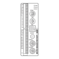
Description of the controller unit's parts and their functions.
Details on Double-Speed Random and CS-Mount camera types.
Information on camera cables and extension cables.
Functions and usage of the operation keypad.
Instructions for connecting external devices like monitor, camera, and keypad.
Guidelines for optimal installation locations and space requirements.
Procedures for mounting the controller unit onto a DIN rail or via screws.
Procedures for mounting the camera and specific notes on correct usage.
Tables for selecting lenses based on view range and resolution.
Methods for attaching wires to terminal blocks correctly and safely.
Specifications and connection examples for parallel output terminals.
Specifications and connection examples for parallel input terminals.
Important considerations for using parallel input and output signals.
Guidelines for safe and effective electric power connection and noise resistance.
Methods for grounding to prevent electrical noise interference.
Description of COM and TOOL ports for serial communication.
Wiring examples for connecting the COM port to PCs and PLCs.
Information on connecting the TOOL port for VBT Ver. 2 and its usage.
Details on six camera modes based on object type, illumination, and camera type.
Explanation of Frame and Field capture modes and their usage for image processing.
Procedures for creating, backing up, and restoring product type and image data.
Detailed technical specifications for the controller unit.
Technical specifications for the operation keypad, including dimensions and environmental limits.
Technical specifications for the ANMA810 monitor, including CRT and frequency.
Detailed technical specifications for the ANM831 camera.
Detailed technical specifications for the ANM832 camera.
List of part numbers for different Micro-Imagechecker A200 and A100 series controllers.
List of part numbers for Double-speed random and CS-mount cameras.
Part numbers for camera cables and extension cables with different lengths and CE compliance.
Part numbers for keypads with varying cable lengths and CE compliance.
Part numbers for monitors, monitor cables, and BNC connectors.
Part numbers for data backup software and PC connection cables.
Part numbers for C mount lenses and adapter rings.
Part numbers for various LED lighting accessories and their components.
Dimensional drawings and measurements for the controller unit.
Dimensional drawings and measurements for the ANM831 camera.
Dimensional drawings and measurements for the ANM832 camera.
Dimensional drawings for camera cables and extension cables.
Dimensional drawings and measurements for the keypad.
Dimensional drawings and mounting notes for the ANMA810 monitor.
Dimensional drawings for various lenses.
Pin assignments and signal names for the ANM831 camera connector.
Pin assignments and signal names for the ANM832 camera connector.
Records of manual updates, including manual number, issue date, and changes.
| Series | A200 Series |
|---|---|
| Category | Machine Vision Systems |
| Camera Type | Monochrome/Color |
| Communication Interface | Ethernet, RS-232C |
| Power Supply | 24V DC |
| Storage Temperature | -20°C to 60°C |
| Lighting | External |
| Operating Temperature | 0°C to 40°C |