Do you have a question about the Panasonic PV500 and is the answer not in the manual?
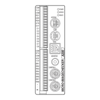
Details the main unit, its connectors, and indicators.
Describes different camera types, their specifications, and precautions for use.
Explains the typical operations and functions of the keypad.
Details the specifications and connection of the XGA monitor.
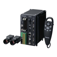
Provides an example of a basic system configuration with two cameras.
Covers the mounting arrangement and notes for installing the PV500 unit.
Guides on selecting lenses, mounting cameras, and notes for mounting.
Details the steps for installing the XGA monitor.
Explains how to connect peripherals like cameras, monitors, and keypads.
Describes how to connect the 24V DC power to the XGA monitor.
Details how to connect the 24V DC power to the PV500 unit.
Covers the process of supplying power after confirming all connections are correct.
Explains the language selection window and basic window operations.
Describes the two main windows (RUN and SETUP) and their basic functions.
Details how to select items, input values, and input characters using the keypad.
Guides on selecting and displaying images from the camera or memory.
Explains how to adjust the magnification and scroll images.
Covers setting inspection ranges and excluded areas using various shapes.
Explains how to copy and output the screen display to a SD card or PC.
Outlines the step-by-step procedure for setting inspection conditions in SETUP menu.
Explains what a Product Type is and how to add, switch, or copy them.
Details how to set camera type, trigger, shutter speed, gain, and other capturing parameters.
Describes how to divide checkers into blocks and select execution modes.
Explains how to save an image processing of the inspection object in memory.
Covers image preprocessing techniques like binarization and filter application.
Introduces various checker types and how to set inspection areas.
Explains how to adjust the position and rotation of checker areas.
Details how to expand or contract inspection areas to fit variable-sized objects.
Explains calculations like distance, intersection points, and angles using detected data.
Covers how to calculate and output detected data using numerical expressions.
Explains how to totally judge results from multiple checkers or calculations.
Describes conditions for saving or outputting images based on inspection results.
Explains how to save inspection images in memory based on NG judgment.
Covers drawing figures and characters on the screen window for display.
Explains how to copy, delete, or replace figures in character/figure drawing.
Guides on how to start and stop the RUN mode for performing inspections.
Details operations available in the RUN menu, including selecting types and managing settings.
Covers setting display contents, window arrangements, and transparency in the RUN menu.
Explains how to save, copy, and delete screen layouts for custom display arrangements.
Guides on how to switch between registered layouts using the keypad or external signals.
Provides an overview of environment settings, including system settings, input/output, camera, color, password, and initialization.
Covers settings related to startup status, operation, and system registers.
Details settings for communication with external devices like parallel I/O and serial ports.
Explains camera type selection and FLASH signal polarity settings.
Covers changing display colors for menus, letters, and backgrounds.
Explains the function of protecting settings with a password.
Describes how to initialize all environment settings to their default values.
Outlines the functions available in the TOOL menu, including settings, information display, and updates.
Covers startup settings, network configuration, calendar, language, and initialization.
Details how to set device names and TCP/IP configurations for Ethernet communication.
Guides on setting the date and time of the built-in clock.
Explains how to change the displayed language of the menus.
Describes how to initialize general settings to their default values.
Supports setting optical parts, communication confirmation, and adjustments.
Covers displaying PV information and upgrading the PV500 firmware.
Lists the main items that can be communicated via I/O interface, including input and output signals.
Details the pin arrangements for I/O connectors and terminal blocks.
Provides instructions on how to wire using discrete wires and special tools.
Explains the main input and output signals and their functions.
Details the timing and conditions for output signals like READY, READ END, FLASH, RESULT, ACCEPT, and TACT.
Illustrates typical operations in inspections, including common and individual triggers.
Covers available communication ports (RS-232C, Ethernet) and protocols.
Details the communication specifications and connector pin assignments for RS-232C.
Explains Ethernet communication specifications, including connector, media, protocol, and baud rate.
Describes the General Purpose Communication and PLC Communication protocols.
Lists and details various commands for controlling the PV500 via RS-232C and Ethernet.
Introduces PVWIN software for setting and simulation, including hardware requirements and download information.
Guides on connecting the PV500 to a PC using USB or Ethernet cables.
Covers uploading and downloading setting data, reading the latest image, and saving/downloading images.
Provides general specifications for the PV500 unit, including CPU, connections, resolution, and environmental resistance.
Lists product numbers for PV500V2, PV500 (V1), Keypad, Cameras, Cables, and Lenses.
Shows the physical dimensions of the PV500 unit and keypad.
Explains how to read commands for Numerical Calculation and Judgement.
Provides an alphabetical list of general communication commands with meanings and refer pages.
| Brand | Panasonic |
|---|---|
| Model | PV500 |
| Category | Machine Vision Systems |
| Language | English |