EasyManua.ls Logo

Panasonic PV500 - Main Function of Signals

Panasonic PV500
494 pages
Print Icon
To Next Page IconTo Next Page
To Previous Page IconTo Previous Page
Loading...
366
Operation and Data Output through I/O Terminals
Chapter 8
8.2.2 I/O Terminal Block
All input signals are also available for I/O connector. Use one of I/O connector and I/O terminal block.
Connecting to the both terminals might damage PV.
The input/output circuit is the same as the I/O connector. See page 364.
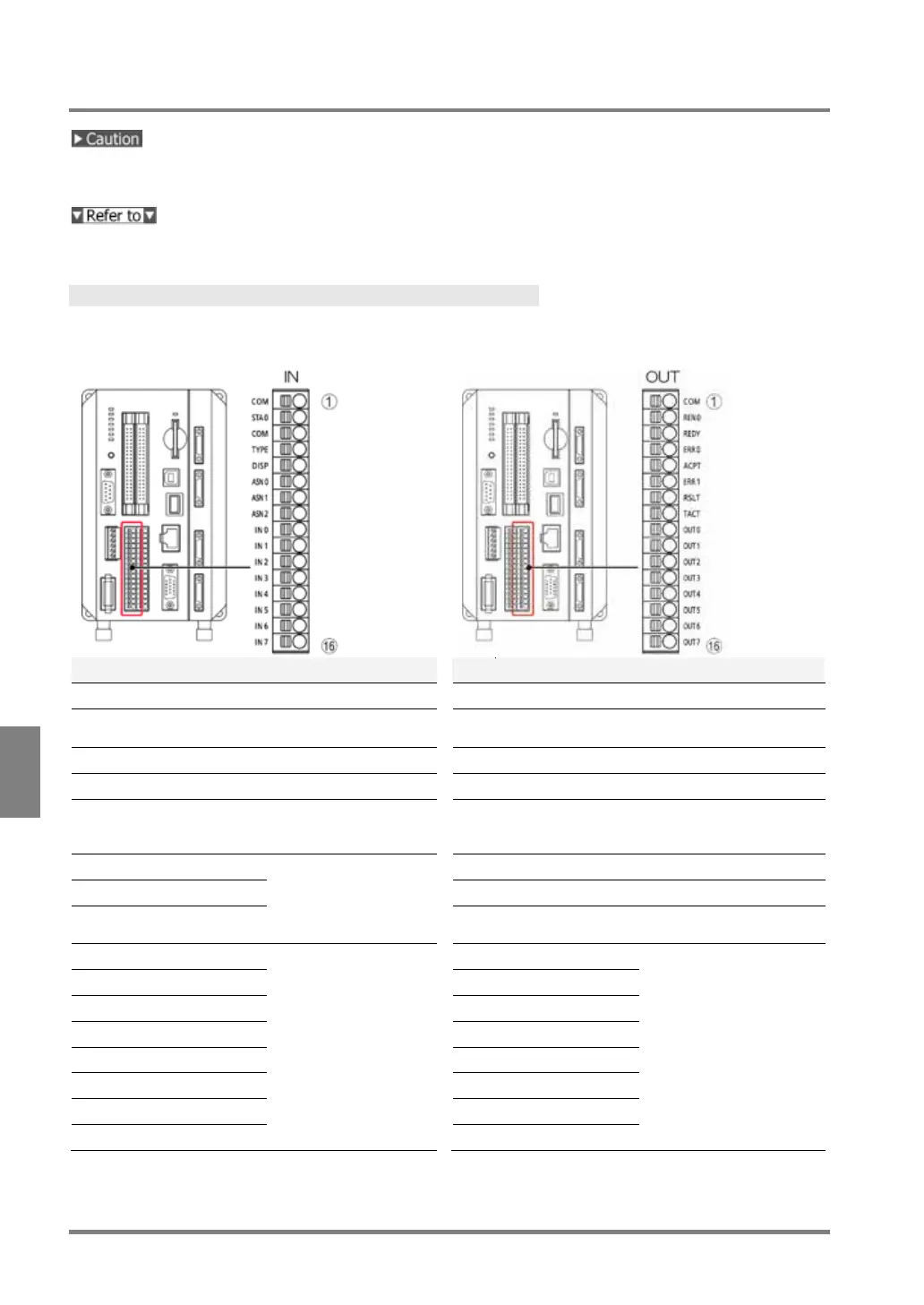
Pin Arrangement
Input
Output
No.
Signal (indication)
Description
No.
Signal (indication)
Description
1
COMMON (COM)
Common for input
1
COMMON (COM)
Common for output
2
START 0 (STA0)
Image capture with
Camera 0
2
READ END 0
(REN0)
Image capture with
Camera 0 complete
3
COMMON (COM)
Common for input
3
READY0 (REDY)
Ready completion signal
4
TYPE (TYPE)
Type Switch
4
ERROR 0 (ERR0)
Error signal 0
5
DISPLAY (DISP)
Layout Switch
5
ACCEPT (ACPT)
Signal* acceptance
(*Type, Display, Reentry,
Assign, Run/Stop)
6
ASSIGN 0 (ASN0)
Function assignment
0-2
(select from 15
functions)
6
ERROR 1 (ERR1)
Error signal 1
7
ASSIGN 1 (ASN1)
7
RESULT (RSLT)
Total Judgement
8
ASSIGN 2 (ASN2)
8
TACT
Reading timing of
inspection data
9
IN 0
Input data 0-7
9
OUT 0
Output data 0-7
10
IN 1
10
OUT 1
11
IN 2
11
OUT 2
12
IN 3
12
OUT 3
13
IN 4
13
OUT 4
14
IN 5
14
OUT 5
15
IN 6
15
OUT 6
16
IN 7
16
OUT 7

Table of Contents