360
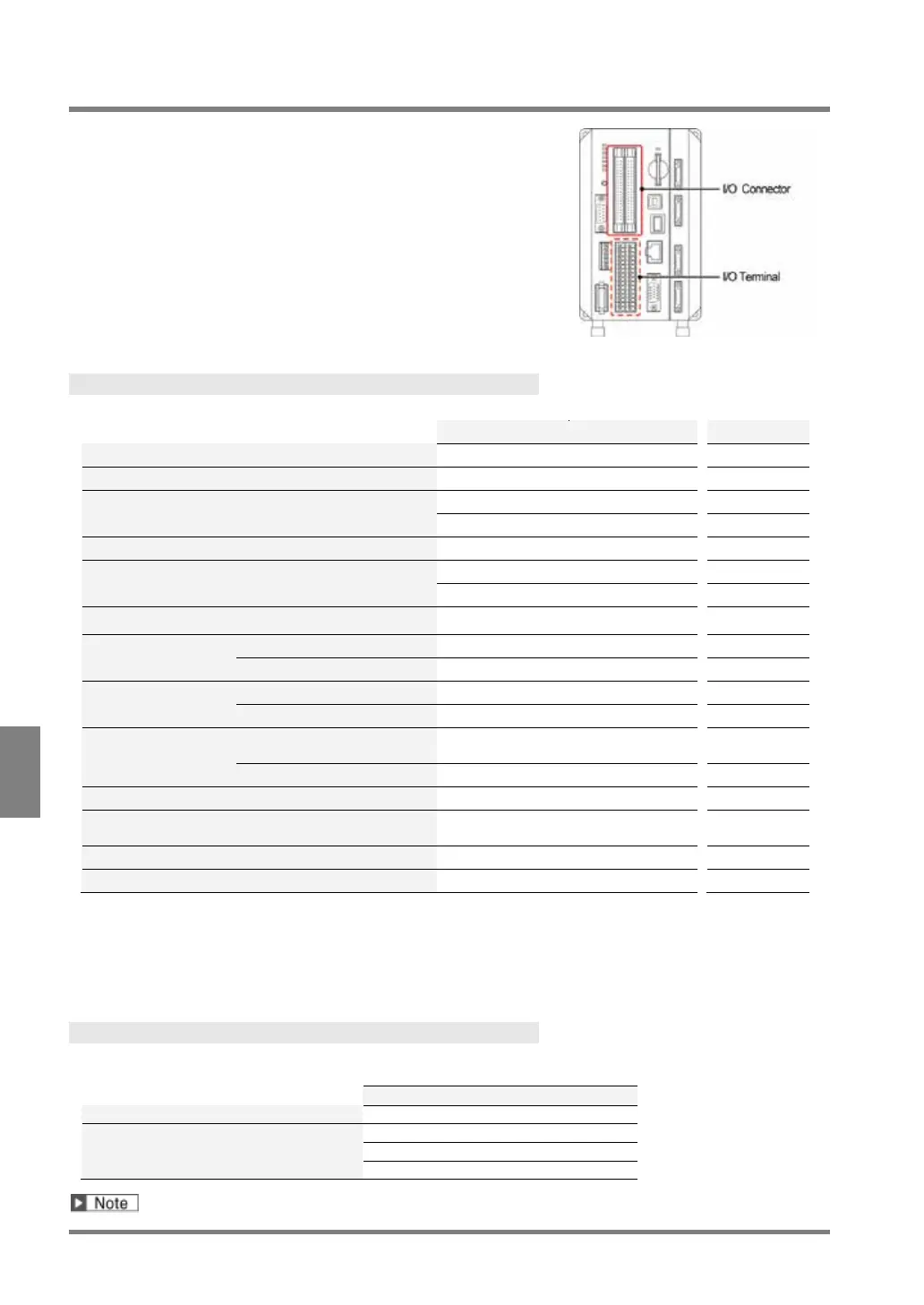
Operation and Data Output through I/O Terminals
8.1 Main Items that can be Communicated through I/O Interface
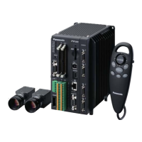
PV500 is provided with I/O interfaces as below.
• I/O connector (MIL connector type)
Input: 32 pins, Output: 32 pins
• I/O terminal block
Input: 14 pins, Output: 15 pins
Input
The operations shown in the table below can be executed by input from the external devices.
%S
%R
%X
%A
%I
%RM
%Q
%E
memory of PV
Save in a SD memory card
(backup)
%SS
Save the latest inspection image in a SD memory
card or PC etc. through Ethernet
---
Abort Save/read Setting Data
*1: Up to six functions are available because six points of ASN0 to 5 are assigned functions. ASN0 to 2 are
common function with I/O terminal block.
*2: Up to three functions are available because three points of ASN0 to 2 are assigned functions. They are
common functions with ASN0 to 2 of I/O connector.
*3: Command to control with interface of RS-232C and Ethernet. Refer to page 396 for details.
Output
The data shown in the table below can be output from PV500 during inspections. “Total Judgement” is output
without condition, however, outputting the other data is selective.
Numerical calculation result
To set whether to output or not, select “ENVIRONMENT” > “Input/Output” > “Parallel I/O Output”.