10
1.1 PV500
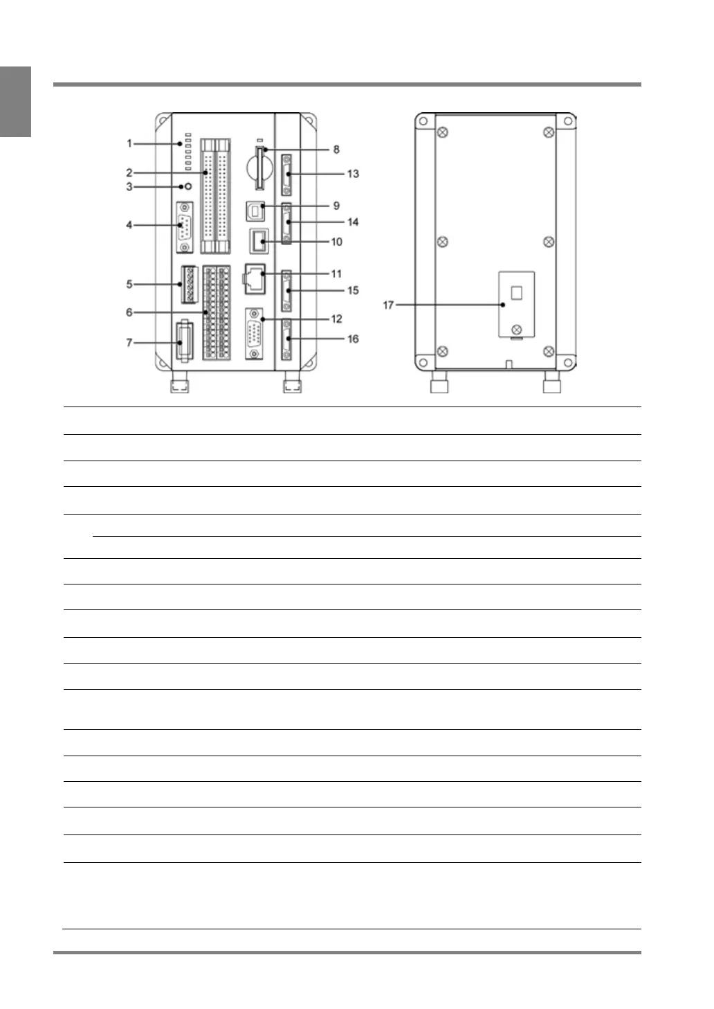
Displays the status of the following signals and communication ports.
POWER / READY / ERROR0 / ERROR1 / COM.0 / COM.1 / COM.2
I/O interface, MIL connector type
RS-232C Communication port.
Connects the cable of D-SUB 9 pin connector.
Parallel I/O Terminal Block
I/O interface, terminal block type
Supplies 24V DC through the included power cable.
Complies with SD memory card (SDHC) with up to 32 GB of memory.
During accessing to a SD memory card, the LED above the slot flashes.
USB 2.0 supported. (Exclusive for PVWIN communication)
Connects a keypad (ANPVP03 / ANPVP10).
Connects an Ethernet cable. When connecting an Ethernet cable, either
one of two LEDs lights. The LED to light and the color varies depending
Analog RGB output terminal. Connects a monitor.
Camera 2 Connect Port
(Only for 4-camera type)
Camera 3 Connect Port
(Only for 4-camera type)
Attaches the battery retaining the following information.
See the next page and attach the battery before use.
- Built-in calendar
- Type No. and Layout No. when turning off the power
- Status of keypad operation
 Loading...