No. Item/Part Fig. Removal(Screw& Other)
1. Front Case Unit&
Bottom Case Unit
Fig. 1-1 5-Screws(A/B/C)
Fig. 1-2 6-Screws(D/E)
Fig.1-3 1-Screw(F)
1-Screw(G)
Fig.1-4 Unlock---(a)
Remove the Bottom Case Unit.
Unlock---(b)
Remove the Front Case Unit.
2. Side Case (R) Unit Fig. 2-1 4-Screws(H/I/J)
Fig. 2-2 Slide the Side Case (R) Unit.
Disconnect the following connectors.
FP601/FP602/FP6302/P4201
Remove the Side Case (R) Unit.
Remove the Top Case Unit.
3. Rear Case Unit
(With EVF Unit)
Fig. 3 Disconnect the following connectors.
FP1001/FP801
Remove the Rear Case Unit.
4. Lens Unit Fig. 3 2-Screws(K/L)
Disconnect the FP701/PP201.
Remove the Lens Unit.
5. Mic Unit Fig. 3 2-Screws(M)
Disconnect the FP4801.
Remove the Mic Unit.
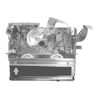
6. Mecha.Unit& VTR
Main/ Power/ DSC
(NV-DS25 Only)
C.B.A.
Fig. 4-1 Disconnect the P1001.
Remove the Power C.B.A.
Disconnect the FP6303/FP6301.
3-Screws(N)
Remove the Mecha.Unit& VTR Main C.B.A.
Disconnect the PS3401/ FP3403.
Removethe DSC C.B.A.
7. VTR Main C.B.A. Fig. 4-2 Disconnect the following connectors.
FP5001/FP2202/FP2203/FP2201/FP2204
Unlocks---(c/d)
Remove the VTR Main C.B.A.
12
 Loading...