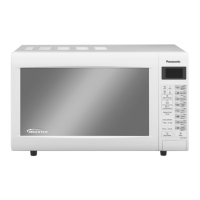
This document provides a comprehensive service manual for the Panasonic NN-GT370M Microwave Oven, detailing its functions, technical specifications, usage, and maintenance procedures.
Function Description
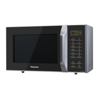
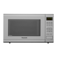
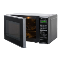
The NN-GT370M is a microwave oven designed for various cooking tasks, including microwave cooking, grilling, and combination cooking. It incorporates an Inverter Power Supply for precise control over microwave output, allowing for variable power cooking. The oven also features Turbo Defrost and Auto Cook functions for automated meal preparation.
Variable Power Cooking Control: The Inverter Power Supply (U) controls the output power based on signals from the Digital Programmer Circuit (DPC). While the power relay remains continuously on, a Pulse Width Modulation (PWM) signal regulates the microwave output. This allows for different power levels:
- High: 100% power, 22 seconds ON, 0 seconds OFF.
- Medium-High: 65% power, 22 seconds ON, 0 seconds OFF.
- Medium: 50% power, 22 seconds ON, 0 seconds OFF.
- Medium-Low: 30% power, 22 seconds ON, 0 seconds OFF.
- Defrost: 30% power, 17 seconds ON, 5 seconds OFF.
- Low: 20% power, 13 seconds ON, 9 seconds OFF.
It's important to note that the ON/OFF time ratio does not directly correspond to the microwave power percentage, as approximately 2 seconds are required for magnetron filament heating.
Inverter Power Supply Circuit: The Inverter Power Supply circuit operates from a 220V AC 50Hz input, rectifying it to DC voltage. This DC voltage is then supplied to IGBT switching devices, which are switched ON-OFF by a 20 to 40 kHz PWM signal from the DPC. This process drives a high voltage transformer, increasing the voltage to 2,000V AC. A half-wave doubler voltage rectifier circuit, comprising H.V. diodes and capacitors, then generates the necessary 4,000V DC for the magnetron. The magnetron's output power is continuously monitored by a current transformer within the inverter circuit, with the signal fed back to the DPC's microcomputer to adjust the PWM signal for output power control.
Turbo Defrost and Auto Cook: When these features are selected, the DPC determines the appropriate power level and cooking time, displaying the operating status. The oven automatically turns off once the cooking time elapses. For example, 1.0 kg of food requires 14 minutes 30 seconds for Turbo Defrost, and 800g of food requires 8 minutes 00 seconds for Auto Reheat.
Grill Cooking Control: Grill cooking utilizes only the upper heaters. A single grill cooking cycle lasts 33 seconds. During this process, the DPC controls the ON-OFF time of power relay RY3, while power relay RY1 remains continuously ON.
Combination Cooking: This mode combines microwave and grill cooking synchronously within a 33-second cycle. The DPC controls the ON-OFF times for both power relay RY3 (grill) and power relay RY1 (microwave).
Important Technical Specifications
- Model: NN-GT370M
- Power Source: 220V AC Single Phase, 50Hz
- Power Consumption:
- Microwave: 1100W
- Heater: 1050W
- Output Power:
- Microwave: 950W
- Heater: 1000W
- Microwave Frequency: 2450MHz
- Timer:
- 30 Min. / Stage (HIGH Power Level) ~ 3 Stage Maximum
- 99 Min. 59 Sec. / Stage (Other Power Level) ~ 3 Stage Maximum
- Outside Dimensions: 488mm(W) x 279mm(H) x 405mm(D)
- Oven Cavity Dimensions: 315mm(W) x 178mm(H) x 353mm(D)
- Net Weight: 10 kg
- PbF: This product is manufactured with PbF (lead-free solder).
Usage Features
- Control Panel: The oven features a user-friendly control panel with a display window, Micro Power Pad, Turbo Defrost Pads, Time Pads, Timer/Clock Pad, Auto Cook Pads, Stop/Reset Pad, and Start Pad.
- Display Window: Shows cooking information, time, and other operational details.
- Beep Sound: A single beep confirms correct pad presses. Two beeps indicate progression between programmed stages, and five beeps signal the completion of a program.
- Automatic Cancellation: If an operation is set but the Start pad is not pressed within 6 minutes, the oven automatically cancels the operation and reverts to clock or colon mode.
- Child Safety Lock: Activated by pressing the Start pad three times.
Maintenance Features
Safety Precautions:
- High Voltage and High Temperature Warning: The Inverter Power Supply operates with extremely high voltage and current. Servicing should only be performed by experienced professional technicians. The aluminum heat sink is energized with high voltage and can be very hot.
- Discharge Capacitors: Always unplug the power cord and discharge high voltage capacitors for about 30 seconds after the oven is turned off before touching any components. This is done by shorting the magnetron filament terminals to the chassis ground with an insulated handle screwdriver.
- Grounding: Ensure proper grounding of the appliance. The inverter grounding bracket must be correctly connected to the chassis to prevent exposure to high voltages.
- Part Replacement: Use only manufacturer-specified parts for critical components (marked with a triangle in the parts list) to prevent microwave leakage, shock, fire, or other hazards. Do not modify the original design.
- Lead-Free Solder (PbF): PCBs manufactured with lead-free solder have a PbF stamp. PbF solder has a higher melting point (30-40°C higher than standard solder), requiring a high-temperature soldering iron (set to 370 ± 10°C). Overheating PbF solder (around 600°C) can cause splashing.
- Sharp Edges: Exercise caution when disassembling or reassembling internal parts due to potential sharp edges.
- Magnetron Installation: After magnetron replacement, ensure mounting screws are properly tightened to prevent microwave leakage. The antenna gasket must be in place.
- Door Assembly Adjustment: Crucial for preventing excessive microwave leakage. The gap between door E and the cavity front plate should be 0.3-0.7mm. The upper portion of the door must firmly touch the oven cavity front plate without pushing the door.
Component Test Procedures:
- Primary, Secondary Latch Switch, and Power Relay RY1: Test continuity with an ohm meter at door opened and closed positions.
- Short Switch: Test continuity with an ohm meter at door opened and closed positions.
- Magnetron: Disconnect leads and check continuity across filament terminals (should be 1 ohm or less) and between each filament terminal and the magnetron case (should read open).
- Inverter Power Supply (U): Do not attempt to repair; replace the complete unit if defective. Test procedures are provided to identify failure codes (H95, H97, H98, H99) related to the inverter and magnetron.
- Temperature Thermistor: Located on the magnetron, it detects overheating. A normal thermistor resistance is 35kΩ to 110kΩ at 10-30°C ambient temperature. The thermistor level can be displayed in TEST MODE (range 16-230).
Disassembly and Parts Replacement Procedures:
- Magnetron: Involves discharging the high voltage capacitor, removing screws for the supporter and air guide A, and then removing the magnetron.
- Digital Programmer Circuit (D.P.C) & Membrane Switch: Requires grounding static electric charge, removing screws for the escutcheon base, disconnecting connectors, and then removing the DPC board. Membrane switch replacement involves careful removal of adhesive tape, often aided by hot air.
- Low Voltage Transformer and/or Power Relays (RY1): Involves disconnecting connectors, removing screws for the DPC board, and carefully desoldering components using a 30W soldering iron (not more than 30W for DPC contacts).
- Fan Motor: Involves disconnecting lead wires, removing screws for the orifice assembly, detaching the fan blade, and then removing the fan motor.
- Door Assembly: Involves supporting the door, removing hinge screws, and carefully disassembling door components.
- Turntable Motor: Involves removing the motor cover, disconnecting lead wires, and removing the motor screw.
- Quartz Heater: Involves disconnecting lead wires, bending locking tabs, and sliding out the heater mounting plate.
Troubleshooting Guide:
- Provides a matrix of symptoms, causes, and corrections for common issues such as the oven stopping operation, no display, fan motor issues, low microwave output, and heater malfunctions.
- Includes specific troubleshooting steps for inverter circuit and magnetron problems, as well as issues related to the Digital Programmer Circuit.
- Details how to check semiconductors (diodes, transistors, IGBTs) using an OHM meter.