Do you have a question about the Panasonic NN-V673SBBPQ and is the answer not in the manual?
Explains auto weight defrost and cook functions with weight settings for various food items.
Step-by-step guide to setting the clock on the digital programmer control panel.
Instructions for performing microwave cooking using power and time settings.
Guide for using the Turbo Reheat function, including time setting and start procedure.
Steps to select a desired program and set weight for auto weight defrost.
Procedure for setting the standing time for delayed cooking functions.
Instructions for setting a delayed start time for cooking programs.
Steps to select grill power, set cooking time, and start the grill function.
How to select grill power and microwave power for combination cooking.
Guide to selecting auto weight cook programs and entering food weight.
Instructions for using the auto sensor cooking feature for the NN-V681 model.
How to set and cancel the demonstration mode for the appliance.
Procedure for setting and cancelling the child lock feature on the appliance.
Explains how inverter power supply controls output based on DPC signals for variable power.
Describes how the DPC controls grill power via relay RY4 and duty cycles.
Details combination cooking using microwave and grill, controlled by DPC and relay 4.
Explains auto control features, determining power level and cooking time by category and weight.
Describes auto sensor cooking as a method to cook without setting power level or time.
Emphasizes the necessity of proper grounding for safe operation and repair.
Warns about high voltage, high current, and hot surfaces on the inverter power supply.
Advises to ensure power cord is removed before replacing any part or component.
Details replacement of latch switches and relay RY1 when a 10A fuse blows.
Caution against inserting foreign objects to prevent microwave leakage.
Steps to confirm correct assembly, tight connections, and check for microwave leakage after repair.
Advises caution regarding sharp edges during unpacking, installation, or moving.
Step-by-step guide for removing and replacing the magnetron, including safety notes.
Instructions for removing and replacing the inverter power supply unit.
Procedure for removing the DPC and membrane keyboard, with grounding precautions.
Steps for desoldering and replacing low voltage transformers and power relays on the DPC.
Procedure for removing and replacing the fan motor assembly.
Detailed steps for disassembling the microwave oven door and reassembling it correctly.
Instructions for removing and replacing the turntable motor, including cover trimming notes.
Steps for disconnecting lead wires and removing the quartz heater assembly.
Guide for removing and installing the steam sensor unit and its components.
Procedure to test latch switches and power relay B continuity for door interlock function.
Steps to test continuity of the short switch with the door open and closed.
Method for diagnosing magnetron issues via continuity checks of filament and case.
Instructions for checking switch continuity on the push button keyboard matrix.
Caution against repairing the inverter power supply; advises replacement of the entire H.V. Inverter Unit.
Warning against measuring high voltage circuitry of inverter or magnetron.
Test procedure to check steam sensor function by setting auto sensor program and observing cooking times.
Steps for installing and adjusting door hook assembly and latch switches for proper alignment.
Recommends a simple method for testing magnetron output via water temperature rise.
Lists parts for the E603L5D10BP DPC AU, including resistors, capacitors, and ICs.
Lists parts for the E603Y5D00BP DPC DU, including diodes, transistors, and connectors.
Lists parts for the E603Y5D00BP DPC AU, including diodes, resistors, and relays.
Lists parts for the E603Y5D00BP DPC DU, including resistors, capacitors, and ICs.
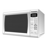
| Brand | Panasonic |
|---|---|
| Model | NN-V673SBBPQ |
| Category | Microwave Oven |
| Language | English |