Do you have a question about the Panasonic NN-V659WB and is the answer not in the manual?
Crucial warnings about high voltage and heat risks associated with the inverter.
Importance of proper grounding for safe operation and repair.
Specific safety precautions for the high-voltage inverter circuit.
Procedure for replacing the high-voltage inverter unit.
Procedure for measuring microwave output power.
| Type | Microwave Oven |
|---|---|
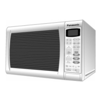
| Color | White |
| Turntable | Yes |
| Preset Programs | Yes |
| Child Lock | Yes |
| Auto Cook | Yes |
| Defrost Function | Yes |
| Keep Warm Function | Yes |
| Power Output | 1000W |
| Microwave Power | 1000W |
| Cooking Modes | Microwave, Grill |