Do you have a question about the Panasonic NV-A3E and is the answer not in the manual?
Details on visual indicators displayed in the viewfinder, including warnings and status.
Information regarding tape end indications and error code display for troubleshooting.
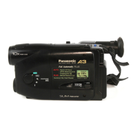
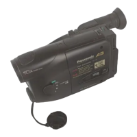
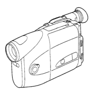
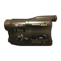
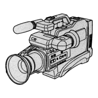
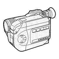
Identification and description of the camcorder's various controls and internal components.
Procedures for inserting, deleting, and manually setting the date and time on the camera.
Instructions for cleaning the movie camera body, lens, and viewfinder.
Explanation of various indicators displayed during shooting and playback modes.
Guidance on setting colour temperature and white balance for optimal image quality.
List and descriptions of optional accessories available for the camera.
Flow chart and step-by-step instructions for disassembling the camcorder units.
Specific instructions for disassembling the lens unit of the camcorder.
Procedures and settings for performing electrical adjustments on the EVF section.
Diagrams and identification of key test points and operational controls on the camcorder.
List of abbreviations used throughout the block diagrams and schematic diagrams.
Schematic diagram illustrating the sensor block and its connections.
Schematic diagram detailing the process block and signal flow within the camcorder.
Block diagram showing the power supply distribution and components.
Schematic diagram for the system control and servo mechanisms.
Diagram showing the physical layout of various circuit boards within the camcorder.
Exploded views illustrating the VTR mechanism components.
Exploded view illustrating the camera lens assembly and its components.
Exploded view illustrating the frame, casing parts, and their assembly.
Comprehensive list of mechanical parts with part numbers, descriptions, and quantities.
Comprehensive list of electrical components with part numbers and specifications.
Overview of the built-in rechargeable lithium battery for the camcorder.
Instructions on how to recharge the camcorder's built-in lithium battery.
Procedures for safely replacing the lithium battery in the camcorder.
Functionality and activation of the OSD line output mode for viewing EVF information on the TV monitor.
Details on Service Mode 1, focusing on battery voltage (A/D value) display and its conditions.
Details on Service Mode 2, focusing on reference voltage A/D value and mechanism position.
Details on Service Mode 3, displaying error codes and conditions for camera issues.
Details on Service Mode 4 for PG shifter value indication for the servo section.
Information on how to display and interpret error codes for diagnostic purposes.