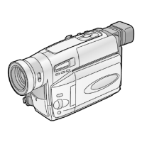
4. PREPARATION FOR ELECTRICAL ADJUSTMENT
1. Unlock the locking tab and remove the EVR connector cover which is
located on Side Case Unit as follows.
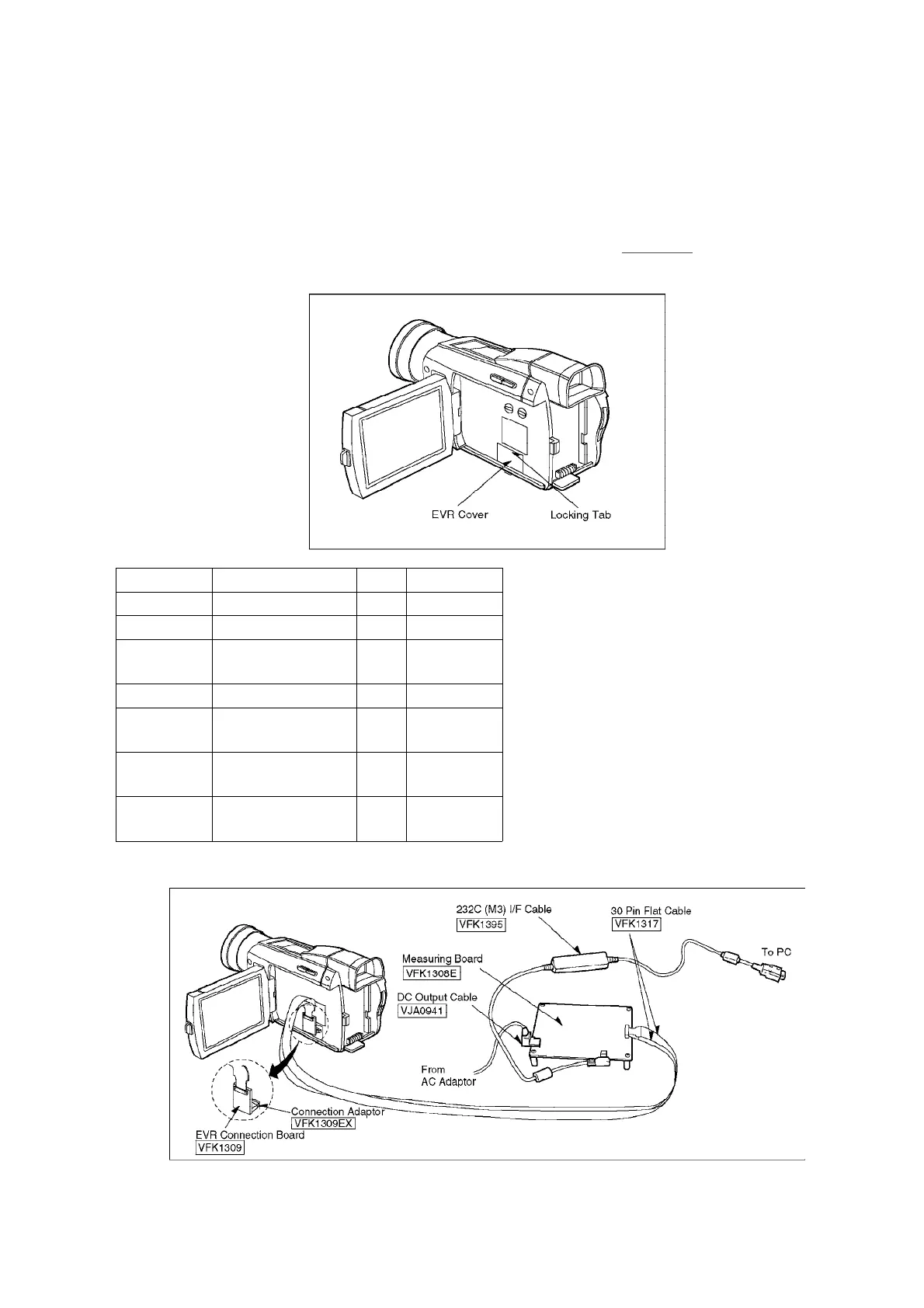
2. Then connect the following cables as shown in
Fig. E2.
Fig. E1
Part No. Part Name Q’ty Remarks
VFK1395 232C(M3)I/F Cable 1
VFK1308E Measuring Board 1
VFK1309 EVR Connector
Board
1
VFK1317 30 Pin Flat Cable 2
VJA0941 DC Output Cable 1 For AC
Adaptor
VFK1164TAR37
Setup Ring 1 For
Collimator
VFK1309EX Connection
Adaptor
1
Fig. E2
Fig. E3
8
 Loading...