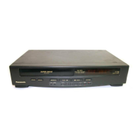
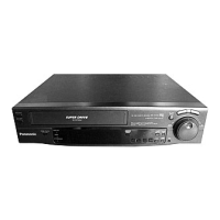
Do you have a question about the Panasonic NV-SD400EU and is the answer not in the manual?
Outlines service procedures, positions, and essential information for technicians.
Details the correct positions for servicing the main C.B.A. and K-Mechanism.
Provides methods for manually removing a cassette tape when electrical circuits fail.
Instructions for correctly installing a flat card cable onto a connector.
Procedure for initializing the channel memory IC after replacement.
Explains how the Service Information Display aids in troubleshooting and repair.
Describes the methods to activate the Service Information Display mode.
Explains the different service modes and their functions for checking circuits.
Details the Service Information Numbers and their meanings for identifying malfunctions.
Provides a timing chart illustrating system control signals for mode switching.
Lists input/output ports and their functions for the IC6001 system control IC.
Provides a step-by-step guide for disassembling the VTR unit.
Details the removal of top and bottom plates during disassembly.
Details procedures for mechanical adjustments, referring to a separate manual.
Refers to a separate manual for mechanism disassembly procedures.
Refers to a separate manual for mechanism assembly procedures.
Provides complete procedures for electrical adjustments of VTR circuits.
Lists the necessary test equipment for performing electrical adjustments.
Outlines preparation steps and selector settings required for adjustments.
Explains how to interpret the format and requirements of adjustment procedures.
Details the procedure for adjusting the PG Shifter for proper timing.
Explains how to adjust slow tracking to minimize noise bars on the monitor.
Details adjustment of luminance and chrominance levels for recording.
Outlines procedures for adjusting video frequency response using a sweep signal.
Describes the SECAM killer adjustment procedure to minimize amplitude.
Details the adjustment of the EE level for video output.
Explains how to adjust the white clip level.
Details the procedure for adjusting playback signal levels.
Outlines the procedure for deviation adjustment, including recording and playback steps.
Details the adjustment of bias current for recording.
Explains how to adjust the timer reference clock using a universal counter.
Lists abbreviations used throughout the service manual.
Illustrates the system control and servo block diagram for motors.
Shows the block diagram for luminance and chrominance signal processing.
Provides the schematic for the main power supply section.
Shows the schematic diagram for the system control and servo sections.
Provides the schematic for luminance, chrominance, and audio sections.
Shows the schematic diagram for the RF section.
Provides the schematic diagram for the On-Screen Display (OSD) pack.
Shows the schematic diagram for the motor drive and sub audio pack.
Provides the schematic diagram for the head amplifier.
Shows the schematic diagram for the timer circuit.
Provides the schematic diagram for the TV demodulator pack.
Presents exploded views of mechanical parts for identification and replacement.
Lists electrical replacement parts with their part numbers and descriptions.


 Loading...