Do you have a question about the Panasonic NV-SD320 and is the answer not in the manual?
Details on channel memory initialization and service position for VCR maintenance.
Information on self-test status indications, often related to mechanical chassis.
Refers to service manual for Z Mechanical Chassis for display information.
Procedure for adjusting the timer reference clock after parts replacement for accuracy.
Important notes and procedures for performing Auto Tuning safely and correctly.
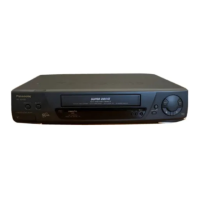
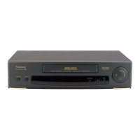
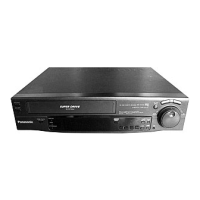
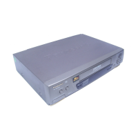
Detailed description of each front and rear control button and connection socket.
Flow chart and details for safely disassembling cabinet parts and circuit boards for servicing.
Refers to the Service Manual for Z Mechanical Chassis for mechanical adjustments.
Procedures and test equipment required for electrical circuit adjustments, including servo section.
List of common abbreviations used in block diagrams and schematic diagrams.
Block diagram illustrating the timer section's circuitry and components.
Block diagram showing the luminance and chrominance signal processing circuits.
Block diagram detailing the system control and servo circuits for VCR operation.
Schematic diagram of the VCR's power supply circuit, including safety warnings.
Main schematic diagram focusing on the system control and servo sections.
Main schematic diagram for luminance, chrominance, and audio processing circuits.
Main schematic diagram covering power supply, OSD, and RF sections.
Main schematic diagram for the VCR's timer and display control circuits.
Main schematic diagram for the cylinder drive motor and servo control circuits.
Schematic diagram of the VCR's head amplifier circuit for signal processing.
Schematic diagram of the cylinder stator unit, including DC voltage chart.
Schematic diagram of the VCR's capstan unit, detailing its drive and control.
Layout diagram of the Main Circuit Board Assembly (C.B.A.) with component references.
Layout diagram of the Power Circuit Board Assembly (C.B.A.) with component references.
Layout diagram of the Head Amp Circuit Board Assembly (C.B.A.) with component references.
Layout diagram of the Capstan Unit with component and connector references.
Exploded view diagram and list of mechanical replacement parts with reference numbers.
Comprehensive list of electrical replacement parts with part numbers and descriptions.