EasyManua.ls Logo

Panasonic OCU-CR200VF5 - User Manual

Panasonic OCU-CR200VF5
52 pages
Print Icon
To Next Page IconTo Next Page
Loading...
ENGLISH
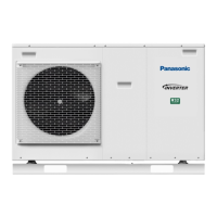
Outdoor Type Refrigeration Unit
(Non- uorocarbon Refrigeration Unit with CO2 Refrigerant)
Operating Instructions and Installation Instructions
Panasonic Corporation
1006 Kadoma, Kadoma City, Osaka, Japan
CONTENTS
Cautions for Safety ....................................................... 2-8
Name of Each Part .......................................................... 9
Scope of Application, Specications ......................... 10-11
For Effectively Using the Refrigeration Unit .............. 12-13
Selection of Installation Location .............................. 13-14
Carry-in / Installation................................................. 14-15
Installation Example ................................................. 16-17
Refrigerant Piping Work ........................................... 17-18
Piping Example.............................................................. 19
Refrigerant Circuit Diagram ........................................... 20
Refrigerant Charging ................................................ 21-22
Cautions for Electrical Wiring Work ............................... 23
Electrical Wiring Work .............................................. 24-25
Electrical Circuit Diagram ......................................... 26-27
What Needs to be Checked before Operation............... 28
Setting and Indication ............................................... 29-33
Control Functions ..................................................... 34-36
Adjustment during Operation .................................... 36-38
About Alarms ............................................................ 38-39
Maintenance and Inspection.......................................... 40
Actions at the time of Failure .................................... 41-42
Failure Diagnosis ...................................................... 43-50
Model No. OCU-CR200VF5 / OCU-CR200VF5SL
Thank you very much for purchasing Panasonic products this time.
Please read this instruction booklet and correctly comply with the explanations.
In particular, please read "Cautions for Safety" (Pages EN2 to EN8) for ensuring safe
operations.
Please retain this instruction booklet in a safe place.
Caution labels are attached to the product.
This illustration represents OCU-CR200VF5
Electrical Approval Certi cate in Australia
CS10793N
• The English text is the original instructions.
Other languages are translation of the original
instructions.
NOTICE
01OCU-CR200VF5.indd101OCU-CR200VF5.indd1 2018/12/2815:17:022018/12/2815:17:02

Other manuals for Panasonic OCU-CR200VF5

Questions and Answers

  • C
    Christian BallSep 23, 2025
    What to do if my Panasonic OCU-CR200VF5 Heat Pump has an inverter anomaly (1st to 9th Trip)?
    • M
      Mrs. Michelle WoodSep 23, 2025
      If your Panasonic Heat Pump is showing an inverter anomaly (1st to 9th Trip), it indicates a hardware anomaly or failure of the inverter-PCB. You should replace the inverter-PCB.
  • W
    watsonsarahAug 23, 2025
    What causes an inverter overload (1st to 9th Trip) in a Panasonic OCU-CR200VF5 Heat Pump, and how can I fix it?
    • J
      jamesmoonAug 23, 2025
      An inverter overload (1st to 9th Trip) in your Panasonic Heat Pump can occur if an overload causes excess current exceeding the protection level, or due to an input power supply anomaly such as a voltage drop. To resolve this, eliminate the cause of the overload or address the anomaly in the power supply.
  • D
    Derek WelchAug 25, 2025
    What does it mean if my Panasonic OCU-CR200VF5 Heat Pump is showing an inverter excess current (1st to 9th Trip)?
    • B
      Betty BrownAug 26, 2025
      If your Panasonic Heat Pump is showing an inverter excess current (1st to 9th Trip), it could be due to an overload causing instantaneous excess current, or a compressor anomaly such as a short-circuit, ground fault, or being locked. To solve this, eliminate the cause of the overload operation or replace the compressor.
  • G
    gardnerannaAug 26, 2025
    How to troubleshoot a Panasonic OCU-CR200VF5 Heat Pump with a gas cooler fan motor anomaly (1st to 9th Trip)?
    • R
      Rachel MullenAug 26, 2025
      If your Panasonic Heat Pump displays a gas cooler fan motor anomaly (1st to 9th Trip), it may be caused by an abnormal fan motor (locked, fan disengaged, or failed) or a wiring anomaly. You should replace the fan motor or fan, or correct the wiring to resolve this issue.
  • J
    Jerry WilliamsAug 27, 2025
    Why does my Panasonic OCU-CR200VF5 Heat Pump show an inverter out of sync (1st to 9th Trip)?
    • C
      Christopher FreemanAug 28, 2025
      An inverter out of sync (1st to 9th Trip) error on your Panasonic Heat Pump is caused by overload. To fix this, eliminate the cause of the overload.
  • R
    Richard SimmonsSep 18, 2025
    What causes an intermediate pressure sensor anomaly in a Panasonic OCU-CR200VF5 Heat Pump?
    • G
      Gregory ClarkSep 18, 2025
      An intermediate pressure sensor anomaly in your Panasonic Heat Pump can be caused by a disconnected or faulty intermediate pressure sensor connector (3P2) or a failure of the sensor itself. To resolve this, ensure the connector (3P2) is correctly attached to the CS1-PCB or pressure sensor side connector, or replace the intermediate pressure sensor.
  • M
    Marcia MerrittSep 15, 2025
    How do I fix a high pressure sensor anomaly on my Panasonic OCU-CR200VF5 Heat Pump?
    • M
      Matthew MartinezSep 15, 2025
      If your Panasonic Heat Pump is showing a high pressure sensor anomaly, it could be due to a disconnected or faulty high pressure sensor connector (3P3), a failure of the high pressure sensor itself, or a failure of the control PCB (CS1-PCB). To resolve this, correctly attach the connector (3P3) to the CS1-PCB or pressure sensor side connector, replace the high pressure sensor, or replace the control PCB (CS1-PCB).
  • L
    Laura ScottSep 16, 2025
    How do I fix a split cycle outlet temperature sensor anomaly on my Panasonic OCU-CR200VF5 Heat Pump?
    • E
      Edward ButlerSep 16, 2025
      If you're experiencing a split cycle outlet temperature sensor anomaly on your Panasonic Heat Pump, it could be due to a disconnected or faulty split cycle outlet temperature sensor connector (2P2) or a failure of the sensor itself. To resolve this, ensure the connector (2P2) is correctly attached to the CS1-PCB, or replace the split cycle outlet temperature sensor.
  • G
    Gary MartinSep 6, 2025
    What causes a refrigeration unit outlet temperature sensor anomaly in a Panasonic OCU-CR200VF5 Heat Pump?
    • R
      Rita HallSep 6, 2025
      A refrigeration unit outlet temperature sensor anomaly in your Panasonic Heat Pump can be caused by a disconnected or faulty refrigeration unit outlet temperature sensor connector (2P4), or a failure of the refrigeration unit outlet temperature sensor itself. To resolve this, ensure the connector (2P4) is correctly attached to the CS1-PCB or replace the refrigeration unit outlet temperature sensor.
  • D
    David HarrisonSep 3, 2025
    What should I do if my Panasonic OCU-CR200VF5 shows an inverter communication anomaly?
    • K
      Kathleen GordonSep 3, 2025
      If your Panasonic Heat Pump is showing an inverter communication anomaly, it could be due to a communication line anomaly (connector disconnected, terminal disconnected, or wire broken) or a hardware failure (CS1-PCB, inverter). To fix this, correct the communication line or replace the control PCB (CS1-PCB) or the inverter-PCB.

Summary

Cautions for Safety

Installation Work Precautions

Guidelines for safe installation, including foundation, securing, and avoiding refrigerant leaks.

Emergency Handling Procedures

Precautions for handling emergencies like leakage, fire, or explosion.

Scope of Application and Specifications

Technical Specifications and Ratings

Detailed technical, performance, and refrigerant specifications for the unit.

For Effectively Using the Refrigeration Unit

Refrigerant Piping Work

Refrigerant Charging Procedures

Service Valve Positions and Charging Method

Explanation of valve positions and step-by-step instructions for charging refrigerant.

Cautions for Electrical Wiring Work

Electrical Safety and Prevention Measures

Key safety measures to prevent electrical shock and fire during wiring.

Electrical Circuit Diagram

Pre-Operation Checks

Setting and Indication

Pressure Setting Adjustments

Procedure for setting and adjusting low pressure control parameters and standard pressure tables.

Control Functions

Low Pressure Control Method

Explanation of how compressor capacity is controlled based on low pressure.

Protective Functions Overview

Overview of various protective functions that stop compressor operation.

Adjustment during Operation

Refrigerant Quantity Adjustment and Pressure Checks

Methods for adjusting refrigerant quantity and checking pressure levels using tables.

About Alarms

Abnormality Alarm Descriptions

Detailed table of alarms, error codes, compressor behavior, and reset methods.

Maintenance and Inspection

Actions at the time of Failure

General Failure Handling Procedures

General precautions and steps to take when a component failure or malfunction occurs.

Failure Diagnosis

Error Code Table Overview

Comprehensive table of error codes, their meanings, causes, and recommended troubleshooting actions.

Sensor Errors Diagnosis

Diagnosis for high pressure, refrigerant flood back, and various temperature/pressure sensor errors.

Inverter System Faults Troubleshooting

Troubleshooting for inverter abnormalities, over current, overload, and step out.

Abnormal Discharge Gas Temperature Diagnosis

Step-by-step guide for diagnosing abnormal discharge gas temperature, including cycle checks.

Sensor Characteristic Checks

Methods for checking the resistance and voltage characteristics of various sensors.

Inverter Unit Failure Diagnosis

Troubleshooting steps for inverter unit failures, including compressor, components, and power voltage issues.

Panasonic OCU-CR200VF5 Specifications

General IconGeneral
CategoryHeat Pump
Heating Capacity5.0 kW
RefrigerantR32
Operating Temperature Range (Cooling)16°C to 43°C
Weight (Indoor Unit)10 kg

Related product manuals