Power
Management
System
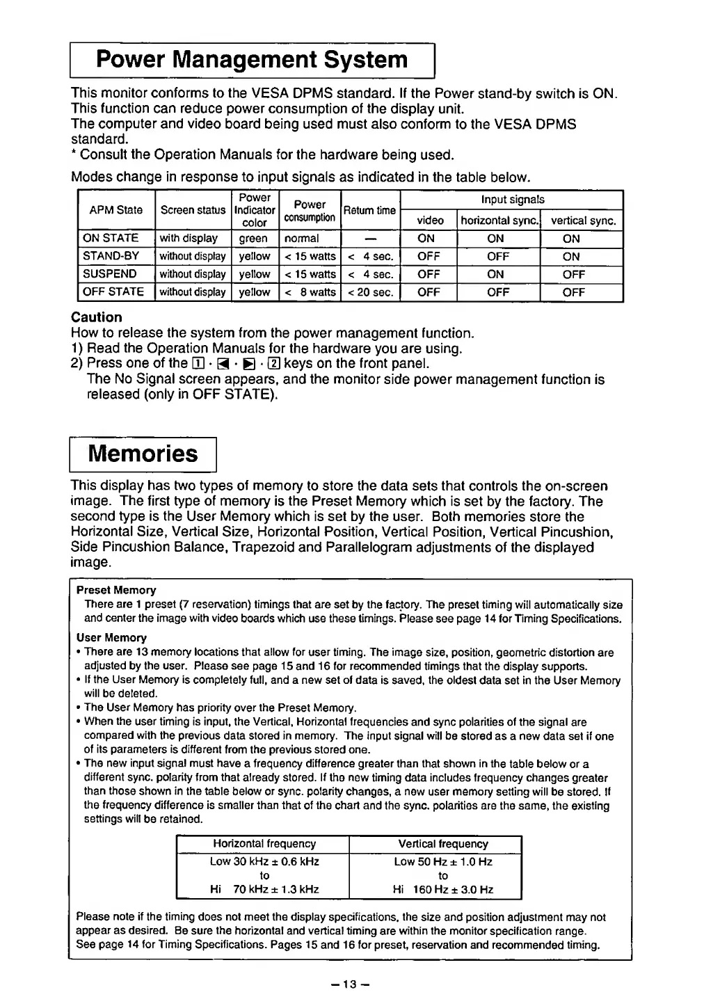
This monitor conforms to the
VESA DPMS
standard. If the Power
stand-by
switch
is ON.
This function can
reduce power consumption of the
display
unit.
The computer and
video board
being used must also conform
to the VESA
DPMS
standard.
*
Consult
the
Operation
Manuals for the
hardware being
used.
Modes
change in
response
to input signals as indicated in the
table below.
APM State
Screen status
Power
Indicator
color
Power
consumption
Return
time
Input signals
video
horizontal sync.
vertical
sync.
ON
STATE with
display
green normal
ON ON
ON
STAND-BY without display
yellow <
15
watts <
4 sec. OFF OFF
ON
SUSPEND without display yellow
< 1
5
watts < 4
sec. OFF ON
OFF
OFF
STATE without
display yellow <
8
watts <
20
sec. OFF OFF OFF
Caution
How to release the system from
the power management
function.
1)
Read
the
Operation
Manuals for the
hardware
you
are using.
2)
Press one
of
the
[D
•
a
•
E
•
LTI
keys on the front panel.
The No Signal screen
appears, and the monitor
side power management function
is
released (only
in
OFF STATE).
Memories
This display has two
types of
memory
to store the data
sets
that
controls
the
on-screen
image.
The
first type of memory
is
the
Preset Memory
which is set by the factory. The
second
type is
the
User Memory
which is set by the user. Both
memories store
the
Horizontal
Size, Vertical
Size, Horizontal Position,
Vertical Position, Vertical Pincushion,
Side Pincushion
Balance, Trapezoid
and
Parallelogram
adjustments of the displayed
image.
Preset Memory
There are
1 preset
(7
reservation)
timings that are set by the factory. The
preset
timing
will automatically size
and center the
image
with
video
boards which use these
timings.
Please
see page
14 for Timing
Specifications.
User
Memory
•
There are 13
memory locations that allow for
user
timing.
The image
size, position, geometric distortion
are
adjusted
by
the user.
Please see page
15
and
16
for
recommended timings
that the display supports.
•
If the User Memory
is completely
full, and a new set of data
is saved,
the
oldest
data set in the User Memory
will
be deleted.
•
The
User
Memory has priority
over
the
Preset Memory.
•
When the
user timing is input, the Vertical,
Horizontal
frequencies and sync polarities of the signal
are
compared with
the previous
data stored in memory. The input
signal will
be stored as a new data set if
one
of its parameters
is
different
from
the previous stored one.
•
The new input signal
must have
a frequency difference greater than that shown in the
table below
or a
different
sync, polarity from that
already
stored.
If
the
new
timing data includes frequency changes
greater
than
those
shown in the table
below or sync, polarity changes,
a new user memory setting will
be stored. If
the
frequency
difference is smaller than that
of
the
chart
and the sync, polarities are the same, the existing
settings will
be
retained.
Horizontal frequency Vertical
frequency
Low
30
kHz
± 0.6 kHz
to
Hi 70 kHz ± 1
.3
kHz
Low
50
Hz ± 1
.0
Hz
to
Hi 160
Hz ±3.0 Hz
Please note if
the
timing
does not meet the display
specifications,
the
size
and position adjustment may not
appear as desired.
Be sure
the
horizontal and vertical timing
are
within the monitor
specification
range.
See page 14 for Timing Specifications.
Pages 15
and 16 for preset, reservation and
recommended
timing.
-
13
-
 Loading...