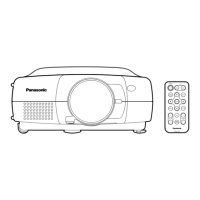
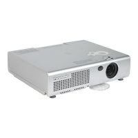
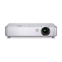
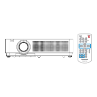
Te rminals
q
w
e
r
e INPUT 3 terminals
VIDEO/Y, Cb/Pb, and Cr/Pr
Connect video or component output signal (Y, Cb/Pb,
and Cr/Pr) from video equipment to these jacks with a
video cable (RCA-type). (p.23, 24)
S-VIDEO
Connect S-Video output signal from video equipment
to this jack. (p.23)
r INPUT 2 terminals
VIDEO/Y, Cb/Pb, and Cr/Pr
Connect video or component output signal (Y, Cb/Pb,
and Cr/Pr) from video equipment to these jacks with a
video cable (BNC-type). (p.24)
G, B, R, H/V, and V
Connect RGB output signal from a computer with a
computer cable (5 BNC-type) to these jacks. (p.22)
w ANALOG OUT
This terminal can be used for analog signal output
incoming through the ANALOG IN terminal (INPUT 1).
Connect this terminal to the other monitor with a VGA
cable. (p.22)
q INPUT 1 terminals
DIGITAL (DVI-D) (HDCP compatible)
Connect digital output signal from a computer or
video equipment to this terminal with a DVI-D cable.
(p.22, 23)
ANALOG IN
Connect analog output signal from a computer or a
video equipment (Component or RGB Scart) to this
terminal with a VGA cable, a Scart-VGA or a
Component-VGA cable. (p.22)
 Loading...