EasyManua.ls Logo

Panasonic PV-D4733S

Panasonic PV-D4733S
98 pages
To Next Page IconTo Next Page
Loading...

Table of Contents

Question and Answer IconNeed help?

Do you have a question about the Panasonic PV-D4733S and is the answer not in the manual?

Panasonic PV-D4733S Specifications

General IconGeneral
BrandPanasonic
ModelPV-D4733S
CategoryDVD VCR Combo
LanguageEnglish

Summary

1 SAFETY PRECAUTIONS

GENERAL GUIDELINES

General guidelines for safe servicing procedures.

LEAKAGE CURRENT COLD CHECK

Procedure to check leakage current with power off.

LEAKAGE CURRENT HOT CHECK

Procedure to check leakage current with power on.

1.1. LASER PRODUCT

LASER Specification

Specifications for the Class I laser product.

1.2. PRECAUTION OF LASER DIODE

2 PREVENTION OF ELECTRO-STATIC DISCHARGE (ESD) TO ELECTROSTATICALLY SENSITIVE (ES) DEVICES

3 ABOUT LEAD FREE SOLDER (PbF)

Distinction of PbF PCB:

Distinguishing features of PCBs manufactured with lead-free solder.

4 SERVICE NOTES (PLEASE READ)

4.1. SERVICE NOTES

Notes and information for servicing the unit.

4.1.2. USAGE SCREEN MODE

4.1.3. EEPROM IC (IC6005), MAIN C.B.A. REPLACEMENT NOTE

4.1.4. GROUNDING FOR ELECTROSTATIC BREAKDOWN

4.1.5. DVD UNIT REPLACEMENT NOTE

4.1.6. METHOD FOR EJECTING THE DVD TRAY MANUALLY

4.1.7. HOW TO UPDATE THE FIRMWARE OF DVD

How to confirm the firmware of DVD:

Steps to confirm the DVD firmware version.

How to update the firmware of DVD:

Procedure for updating the DVD firmware.

4.1.8. SERVICE POSITION

4.1.8.1. Service Position

Procedures for service position 1.

4.1.8.1.1. Service Position (1)

Details for service position 1.

4.1.8.1.2. Service Position (2)

Details for service position 2.

4.1.8.1.3. Service Position (3)

4.1.9. HOT CIRCUIT

4.1.10. SERVICE MODE

4.1.11. TRACKING CENTER MODE (TRACKING FIX AT CENTER)

4.1.12. CAUTION FOR INSTALLATION OF FRONT PANEL ASSY

4.1.13. METHOD FOR LOADINGUNLOADING OF MECHANISM

4.1.13.1. (Manual Method)

Manual method for loading/unloading mechanism.

4.1.13.2. (Electrical Method)

4.1.13.2.1. WHEN LOADING WITHOUT A CASSETTE

Procedure for loading without a cassette.

4.1.14. HOW TO REMOVE A JAMMED TAPE

4.1.14.1. Manual Method

Manual steps to remove a jammed tape.

Method -1:

Method 1 for jammed tape removal.

Method -2:

Method 2 for jammed tape removal.

Method -3:

Method 3 for jammed tape removal.

4.1.14.2. Electrical Method

4.1.15. F.P.C. CONNECTION NOTE

4.1.15.1. F.P.C. between the Capstan Motor and the Cylinder

Note on F.P.C. connection between motor and cylinder.

4.1.15.2. F.P.C. between the DVD Unit (DVD Main C.B.A.) and the Main C.B.A.

Note on F.P.C. connection between DVD and main boards.

4.1.16. BLACK SCREWS ON THE CHASSIS

4.1.17. HOW TO RESET ALL MEMORY FUNCTIONS

4.1.18. HOW TO CONFIRM AUTO CLOCK SET FEATURE

4.1.19. VARIABLE VOLTAGE ISOLATION TRANSFORMER

4.1.20. SPECIAL NOTE

4.1.21. MODEL NO. IDENTIFICATION MARK

5 DISASSEMBLYASSEMBLY PROCEDURES

5.1. CABINET SECTION

Flowchart for cabinet disassembly.

5.1.1. Notes in chart

1. Removal of Top Cover

Steps for removing the top cover.

2. Removal of Front Panel Assy

Steps for removing the front panel assembly.

Installation of Front Panel Assy

Procedure for installing the front panel assembly.

3. Installation of VCR Chassis Unit

Steps for installing the VCR chassis unit.

4. Removal of DVD Sub C.B.A.

Steps for removing the DVD Sub C.B.A.

Installation of DVD Main C.B.A. and DVD Sub C.B.A.

Procedure for installing DVD Main and Sub C.B.A.

5. Installation of Mechanism Chassis and Cassette Up Assy onto Main C.B.A.

Installation of mechanism and cassette assembly onto Main C.B.A.

6. Connection of Mechanism Chassis

Steps for connecting the mechanism chassis.

5.2. MECHANISM SECTION

5.2.1. DisassemblyReassembly Method

Method for disassembling and reassembling the mechanism.

5.2.2. Inner Parts Location

TOP VIEW

Illustration showing inner parts location from the top.

BOTTOM VIEW

Illustration showing inner parts location from the bottom.

5.2.3. EJECT Position Confirmation

5.2.4. Full Erase Head and Cylinder Unit

5.2.4.1. Reassembly Notes

Notes for reassembling the cylinder unit.

5.2.5. Capstan Belt, Support Angle, Intermediate Gear B, and Main Cam Gear

5.2.5.1. Reassembly Notes

1. Alignment of Main Cam Gear, Drive Rack Arm, and Main Rod

Alignment of main cam gear, drive rack arm, and main rod.

3. Holes on Main Cam Gear

Information on holes on the main cam gear for alignment.

5. Installation of Main Cam Gear and Main Cam Push Nut

Procedure for installing main cam gear and push nut.

5.2.6. Center Clutch Unit, Changing Gear Spring, Changing Gear, and Idler Arm Unit

5.2.6.1. Reassembly Notes

Notes for reassembling mechanism sub-assemblies.

5.2.7. Reel Gear, Main Rod, and SS Brake Arm Unit

5.2.7.1. Reassembly Notes

Notes for reassembling mechanism parts.

5.2.8. Capstan Motor Unit

5.2.9. T Loading Arm Unit and S Loading Arm Unit

5.2.9.1. Reassembly Notes

Notes for reassembling loading arm units.

5.2.10. T Brake Unit, Tension Control Arm Unit, T Reel Table, S Reel Table, and Tension Arm Unit

5.2.10.1. Reassembly Notes

Notes for reassembling brake and tension units.

5.2.11. Loading Post Base -T Unit and Loading Post Base -S Unit

5.2.12. Opener Piece, Drive Rack Arm, Pinch Arm Unit, P5 Arm Unit, and Intermediate Gear A

5.2.12.1. Reassembly Notes

Notes for reassembling mechanism components.

5.2.13. Motor Block Unit, Audio Control Head Unit, Lift Gear, Tension Arm Boss, and Cleaner Arm Unit

5.3. CASSETTE UP ASSEMBLY SECTION

5.3.1. Top Plate, Wiper Arm Unit, and Holder Unit

Details on top plate, wiper arm, and holder unit.

5.3.1.1. Reassembly Notes

1. Alignment of Wiper Arm Unit and Drive Rack Unit

Alignment of wiper arm and drive rack units.

2. Installation of Holder Unit

Steps for installing the holder unit.

5.3.2. Opener Lever and Drive Rack Unit

6 ADJUSTMENT PROCEDURES

6.1. SERVICE FIXTURES AND TOOLS

List of service fixtures and tools required for adjustments.

6.2. MECHANICAL ADJUSTMENT

6.2.1. CLEANING PROCEDURE FOR THE UPPER CYLINDER UNIT

Cleaning procedure for the upper cylinder unit.

6.2.2. ADJUSTMENT PROCEDURES

General adjustment procedures.

6.2.2.1. BACK TENSION CONFIRMATION

Procedure to confirm and adjust back tension.

6.2.2.2. TAPE INTERCHANGEABILITY ADJUSTMENT

6.2.2.2.1. ENVELOPE OUTPUT ADJUSTMENT

Procedure for adjusting envelope output.

6.2.2.2.2. AUDIO CONTROL HEAD TILT ADJUSTMENT

6.2.2.2.3. AUDIO CONTROL HEAD HEIGHT ADJUSTMENT

6.2.2.2.4. AUDIO CONTROL HEAD AZIMUTH ADJUSTMENT

6.2.2.2.5. AUDIO CONTROL HEAD HORIZONTAL POSITION ADJUSTMENT

6.3. ELECTRICAL ADJUSTMENT

6.3.1. TEST EQUIPMENT

List of test equipment for electrical adjustments.

6.3.2. HOW TO READ THE ADJUSTMENT PROCEDURES

Guide on reading adjustment procedures.

6.3.3. DVD LUMINANCE LEVEL ADJUSTMENT

6.3.4. EVR (Electronic Variable Resister) ADJUSTMENT WITH THE REMOTE CONTROL

6.3.5. PG SHIFTER ADJUSTMENT

6.4. TEST POINTS AND CONTROL LOCATION

FUNCTION OF IMPORTANT TEST POINTS

Description of important test points.

7 SCHEMATIC DIAGRAMS

7.1. SCHEMATIC DIAGRAM & CIRCUIT BOARD LAYOUT NOTES

Notes and guidelines for schematic diagrams and circuit board layouts.

7.2. MAIN SCHEMATIC DIAGRAMS

MAIN I (SYSTEM CONTROLSERVO) SCHEMATIC DIAGRAM

Schematic diagram for the main system control and servo section.

IO CHART OF IC6001

MAIN II (SIGNAL PROCESSAUDIO) SCHEMATIC DIAGRAM

IC3001 IC-DETAIL BLOCK DIAGRAM

MAIN III (OPERATION) SCHEMATIC DIAGRAM

MAIN IV (Hi-Fi) SCHEMATIC DIAGRAM

MAIN V (POWER SUPPLY) SCHEMATIC DIAGRAM

MAIN VI (5.1 ch AUDIO) SCHEMATIC DIAGRAM

7.3. OPERATION IOPERATION II SCHEMATIC DIAGRAMS

OPERATION I SCHEMATIC DIAGRAM

Schematic diagram for Operation I.

OPERATION II SCHEMATIC DIAGRAM

Schematic diagram for Operation II.

7.4. DVD MAIN SCHEMATIC DIAGRAMS

DVD MAIN I SCHEMATIC DIAGRAM

Schematic diagram for DVD Main I.

IO CHART OF IC8002

IO CHART OF IC8003

DVD MAIN II SCHEMATIC DIAGRAM

IO CHART OF IC8201

IO CHART OF IC8202

IO CHART OF IC8204

DVD MAIN III SCHEMATIC DIAGRAM

IC8501 IC-DETAIL BLOCK DIAGRAM

IC8502 IC-DETAIL BLOCK DIAGRAM

DVD MAIN IV SCHEMATIC DIAGRAM

IC8801 IC-DETAIL BLOCK DIAGRAM

DVD MAIN V SCHEMATIC DIAGRAM

7.5. DVD SUB SCHEMATIC DIAGRAM

DVD SUB SCHEMATIC DIAGRAM

Schematic diagram for DVD Sub.

7.6. INTERCONNECTION SCHEMATIC DIAGRAM

7.7. VOLTAGE CHART

MAIN C.B.A. (POWER SUPPLYVIDEOAUDIO SECTION)

Voltage chart for the Main C.B.A. power supply, video, and audio sections.

OPERATION II

MAIN C.B.A. (SYSTEM CONTROLSERVO SECTION)

DVD MAIN C.B.A.

DVD SUB C.B.A.

8 CIRCUIT BOARD LAYOUT

8.1. MAIN C.B.A.

Layout diagram for the Main C.B.A.

8.1. MAIN C.B.A.

MAIN C.B.A. LSEP2082 HA (A,B,C) LSEP2082 HB (D)

Layout for Main C.B.A. LSEP2082HA/HB.

8.2. OPERATION IOPERATION II C.B.A.

OPERATION I C.B.A. LSEP2092 A

Layout for Operation I C.B.A.

OPERATION II C.B.A. LSEP2093 A

Layout for Operation II C.B.A.

8.3. DVD MAIN C.B.A.

DVD MAIN C.B.A. LSEP2091 B (A) LSEP2091 C (B,C,D)

Layout for DVD Main C.B.A. LSEP2091B/C.

8.4. DVD SUB C.B.A.

DVD SUB C.B.A. LSEP2014 A

Layout for DVD Sub C.B.A. LSEP2014A.

9 BLOCK DIAGRAMS

POWER SUPPLY BLOCK DIAGRAM

Block diagram of the power supply unit.

VIDEO SIGNAL PATH BLOCK DIAGRAM

AUDIO SIGNAL PATH BLOCK DIAGRAM

SYSTEM CONTROL BLOCK DIAGRAM

SERVO BLOCK DIAGRAM

DVD I BLOCK DIAGRAM

DVD II BLOCK DIAGRAM

Troubleshooting Hints

1) Confirm DVD operation and VCR operation

Confirmation of DVD and VCR operation.

How to confirm whether DVD Mechanism Unit or DVD Main C.B.A. is defective.

Steps to differentiate DVD mechanism and main board defects.

Troubleshooting Hints of DVD Mechanism Unit

Hints for troubleshooting DVD mechanism issues.

Cause: Tray Problem

Troubleshooting steps for tray problems.

Cause: Spindle Motor Problem

Cause: Pickup Problem

Cause: Traverse Problem

10 EXPLODED VIEWS

10.1. MECHANISM (TOP) SECTION

Exploded view of the mechanism top section.

10.2. MECHANISM (BOTTOM) SECTION

2 MECHANISM (BOTTOM) SECTION

Exploded view of the mechanism bottom section.

10.3. CASSETTE UP COMPARTMENT SECTION

3 CASSETTE UP COMPARTMENT SECTION

Exploded view of the cassette up compartment.

10.4. CHASSIS FRAME AND CASING PARTS SECTION

4 CHASSIS FRAME AND CASING PARTS SECTION

Exploded view of chassis frame and casing parts.

10.5. PACKING PARTS AND ACCESSORIES SECTION

5 PACKING PARTS AND ACCESSORIES SECTION

List of packing parts and accessories.

11 REPLACEMENT PARTS LISTS

11.1. REPLACEMENT NOTES

General notes for replacing parts.

11.1.1. General Notes

General guidelines for part replacement.

11.1.2. Mechanical Replacement Notes

Specific notes for mechanical part replacement.

11.1.3. Electrical Replacement Notes

Specific notes for electrical part replacement.

11.2. MECHANICAL REPLACEMENT PARTS LIST

COMPARISON CHART OF MODELS & MARKS

Chart comparing models and their marks.

Definition of Parts supplier:

Definitions of parts suppliers.

MECHANICAL REPLACEMENT PARTS LIST

Detailed list of mechanical replacement parts.

11.3.1. MAIN C.B.A.

INTEGRATED CIRCUITS

List of integrated circuits for replacement.

TRANSISTORS

List of transistors for replacement.

PRINTED CIRCUIT BOARD ASSEMBLY

List of replacement printed circuit boards.

DIODES

RESISTORS

CAPACITORS

FILTERS

COILS

CRYSTAL OSCILLATOR

FUSE & PROTECTOR

TRANSFORMER

JACKS

11.3.2. OPERATION I C.B.A.

RESISTORS

List of replacement resistors for Operation I C.B.A.

PIN HEADERS

SWITCHES

SWITCHES

JACKS

11.3.3. OPERATION II C.B.A.

RANSISTORS

List of replacement transistors for Operation II C.B.A.

DIODES

RESISTORS

11.3.4. DVD MAIN C.B.A.

COMPARISON CHART OF MODELS & MARKS

Chart comparing models and their marks.

INTEGRATED CIRCUITS

List of replacement integrated circuits for DVD Main C.B.A.

PIN HEADERS

11.3.5. DVD SUB C.B.A.

SWITCHES

List of replacement switches for DVD Sub C.B.A.
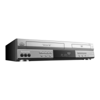
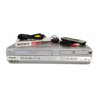
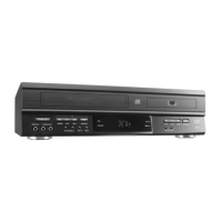
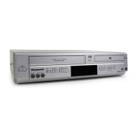
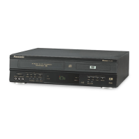
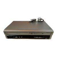
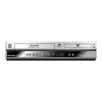
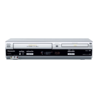
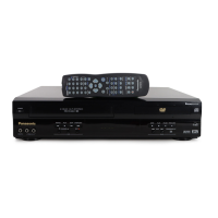
Related product manuals