will appear on the TV monitor.
Fig. E3-1
3. Connect the channel-1 scope probe to TP3001 and the channel-2
scope probe to TP6205. Used TP6205 as a trigger.
4. Adjust value so that the trailing edge of the head switching pulse
is placed 6 H±0.5 H (0.38 ms±0.03 ms) before the start of the
vertical sync pulse by pressing CH UP and CH DOWN buttons on
the remote control.
Fig. E3-2
5. After adjustment is completed, press REC button on the remote
control. Then " COMP " will appear on the TV monitor and
adjusted value will be written to Memory IC (IC6005).
Fig. E3-3
6. Press STOP button on the remote control to release from EVR PG
SHIFTER ADJUSTMENT MODE.
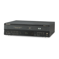
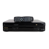
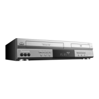
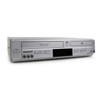
6.4. TEST POINTS AND CONTROL LOCATION
53
 Loading...