Do you have a question about the Panasonic PV-DF2035 and is the answer not in the manual?
Provides essential safety rules for servicing the unit.
Procedure to check for hazardous leakage current with the set off.
Procedure to check for hazardous leakage current with the set on.
Tests the X-ray protection circuit for horizontal oscillator disable.
Explains the function of the horizontal oscillator disable circuit.
Techniques to prevent damage to sensitive devices from ESD.
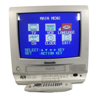
How to access and interpret the unit's self-diagnostic codes.
Steps to access different DVD service modes for diagnostics.
Guidance on diagnosing DVD mechanism issues using service mode.
Steps for setting Service Position 1 for VCR/DVD chassis.
Steps for setting Service Position 2 for VCR/DVD chassis.
Guidance on connecting FFCs between mechanism and main board.
Step-by-step guide for disassembling the unit's cabinet.
Lists necessary tools and fixtures for performing adjustments.
Lists essential equipment for electrical adjustments.
Details on adjusting Electronic Variable Register settings using the remote.
Notes and conventions for reading schematic and layout diagrams.
Detailed schematic of the main circuit board, section I.
Schematic diagram for the deflection circuitry.
Schematic for operation and CRT sections for specific models.
Schematic diagram for the DVD main board, section I.
Schematic diagram for the DVD sub circuit board.
Shows how different circuit boards are interconnected.
Table listing voltage readings for ICs and test points on the main board.
Table listing voltage readings for video/audio sections on the main board.
Table listing voltage readings for the DVD main board.
Table listing voltage readings for the DVD sub circuit board.
Component layout diagram for the main circuit board.
Component layout diagram for the operation circuit board.
Component layout diagrams for deflection and CRT circuit boards.
Component layout diagrams for DVD main and sub circuit boards.
Illustrates the flow of power within the unit.
Shows the signal flow for video processing.
Shows the signal flow for audio processing.
Diagram of the system control and microcontroller functions.
Illustrates the servo control system for disk mechanisms.
Block diagram for the DVD I section.
Block diagram for the DVD II section.
Guide to diagnose issues with DVD or related circuits.
Specific hints for diagnosing DVD mechanism unit faults.
Troubleshooting steps for pickup mechanism issues.
Diagram showing test points on the DVD main board.
Diagram showing the assembly of the mechanism section parts.
Diagram showing the assembly of the DVD section parts.
Diagram of chassis frame parts and their assembly, part 1.
General guidelines and safety notices for replacing parts.
Lists replacement integrated circuits with part numbers.
Lists replacement transistors with part numbers.
Lists replacement diodes with part numbers.
Lists replacement resistors with part numbers.
Lists replacement capacitors with part numbers.
Lists replacement filters, coils, pin headers, and switches.
Lists parts for the Operation Circuit Board.
Lists parts for the CRT Circuit Board (A,B,C models).
| Type | TV VCR Combo |
|---|---|
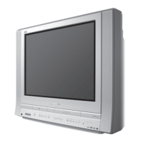
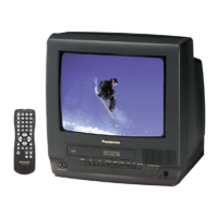
| Brand | Panasonic |
| Model | PV-DF2035 |
| Screen Size | 20 inches |
| Screen Type | CRT |
| VCR Type | 4-Head VCR |
| Tuner | NTSC |
| Remote Control | Yes |
| Comb Filter | Yes |
| Inputs | Composite Video |
| Outputs | Composite Video |