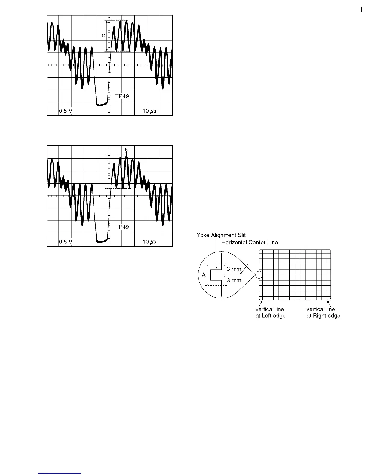
Fig. E5-2
6. Select SUB TINT in EVR adjustment mode and increase
level B 1 clicks above the same level.
Fig. E5-3
7. Select SUB BRIGHT in EVR adjustment mode and reset to
the original value.
7.3.10. DEFLECTION DISTORTION
CORRECTION ADJUSTMENT
Purpose : To set the optimum picture.
Symptom of
Misadjustment :
The picture is distortion.
Test Point : ----------
Adjustment : V POSITION (EVR),
V SIZE (EVR),
H-CENTER (EVR),
(For model with 27 inch CRT)
R763 (Deflection C.B.A.),
R753 (Deflection C.B.A.),
R766 (Deflection C.B.A.)
Specification : Refer to descriptions below.
Input : Video Input Jack,
Crosshatch Pattern Signal,
Monoscope Pattern Signal
Mode : STOP
Equipment : NTSC Video Pattern Generator
1. Supply a Crosshatch Pattern Signal to the Video Input Jack.
2. Confirm that the Horizontal Center Line is within the limits of
A.
Fig. E6-1
3. (For model with 27 inch CRT)
Adjust R763 so that vertical lines should be almost straight.
4. (For model with 27 inch CRT)
Adjust R753 so that vertical lines at Left edge and Right
edge should be almost straight.
5. Supply a Monoscope Pattern Signal to the Video Input
Jack.
6. Select V POSITION in EVR adjustment mode and adjust
Horizontal Center Line is within the limits of A.
31
PV-DF205 / PV-DF2035 / PV-DF275 / PV-DF2735 / PV-DF2035-K / PV-DF2735-K
 Loading...