A. Do not attempt to lift the component off the board until the
component is completely disconnected from the board by a
twisting action.
B. Be careful not to break the copper foil on the printed circuit
board.
Fig. 10-1
3. Installing the leadless component
A. Presolder the contact points on the circuit board.
Fig. 10-2
B. Press the part downward with tweezers and solder both
electrodes as shown below.
Fig. 10-3
Note:
Do not glue the replacement leadless component to the circuit
board.
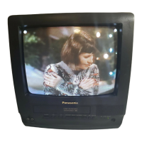
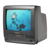
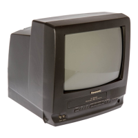
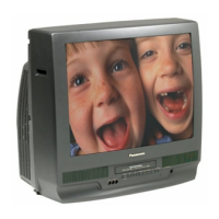
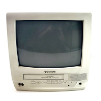
5.1.19. MODEL NO. IDENTIFICATION MARK
Use Marks shown in the chart below to distinguish the different models included in this Service
Manual.
22
 Loading...
