Do you have a question about the Panasonic QUASAR PV-C1320 and is the answer not in the manual?
Special components marked for safety; use manufacturer parts to prevent hazards.
Techniques to prevent damage to sensitive electronic components from static electricity.
Adjustments for sub contrast, focus, screen, cut-off, drive, color, tint, purity, convergence, height, position, white balance, and brightness.
Schematic diagrams for various main boards including system control, signal process, audio, power supply, and CRT.
Circuit board layouts for main boards, showing component placement.
Exploded views of mechanism, cassette compartment, and chassis frame sections.
Comprehensive lists of mechanical and electrical replacement parts with notes.
Schematic diagram for Main I board covering system control, servo, operation, and cylinder drive.
Schematic diagram for Main II board covering signal process, OSD, and audio.
Schematic diagram for Main III board covering TV Y/C process.
Schematic diagram for Main IV board (Audio Amp) for specific models.
Schematic diagram for Main V board covering the power supply.
Block diagrams illustrating various system paths like power supply, video, audio, system control, servo, and TV/YC process.
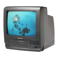
| Type | TV VCR Combo |
|---|---|
| Screen Size | 13 inches |
| Television System | NTSC |
| Audio Output | Mono |
| TV Type | CRT |
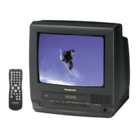
| Remote Control | Yes |
| Inputs | Composite |
| Outputs | Composite |
| VCR Type | 2-Head Mono |