EasyManua.ls Logo

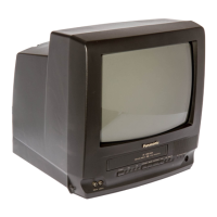
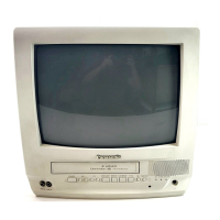
Panasonic Quasar Omnivision PVQ-1311

Panasonic Quasar Omnivision PVQ-1311
247 pages
To Next Page IconTo Next Page
Loading...
ORDER NO. MKE0101101C1
B3
Combination VCR
PVQ-1311 / PV-C1321 / PV-C1331W / VV-1301 / VV-1311W /
PV-C1341 / PV-C1351W / PV-C2011 / PV-C2021 / PV-C2031W
/ VV-2001 / PV-C2061
SPECIFICATIONS
1
Question and Answer IconNeed help?

Do you have a question about the Panasonic Quasar Omnivision PVQ-1311 and is the answer not in the manual?

Panasonic Quasar Omnivision PVQ-1311 Specifications

General IconGeneral
BrandPanasonic
CategoryTV VCR Combo
Display TypeCRT
Audio OutputMono
ModelPVQ-1311
Screen Size13 inches
VCR TypeVHS
TunerNTSC
InputsRF, Composite
OutputsRF, Composite

Summary

SPECIFICATIONS

SAFETY PRECAUTIONS

GENERAL GUIDELINES

Fundamental safety principles for operating and maintaining the device.

X-RADIATION

PREVENTION OF ELECTROSTATIC DISCHARGE (ESD) TO ELECTROSTATICALLY SENSITIVE (ES) DEVICES

SERVICE NOTES (PLEASE READ)

SIMPLIFIED FAULT FINDING DATA

Diagnostic codes and communication data for identifying and resolving faults.

SERVICE MODE

HOW TO REMOVE A JAMMED TAPE

REPLACEMENT PROCEDURE FOR LEADLESS (CHIP) COMPONENTS

DISASSEMBLYASSEMBLY PROCEDURES

CABINET SECTION

Procedures for removing and reinstalling the unit's outer casing.

Inner Parts Location

EJECT Position Confirmation

Reassembly Notes

Capstan Belt, Support Angle, Intermediate Gear B, and Main Cam Gear

Center Clutch Unit, Changing Gear Spring, Changing Gear, and Idler Arm Unit

Stopper Angle, Capstan Rotor Unit, Oil Seal, Capstan Stator C.B.A., and MR Head

T Loading Arm Unit and S Loading Arm Unit

T Brake Unit, Tension Control Arm Unit, T Reel Table, S Reel Table, and Tension Arm Unit

Opener Piece, Drive Rack Arm, Pinch Arm Unit, P5 Arm Unit, and Intermediate Gear A

CASSETTE UP ASSY SECTION

Top Plate, Wiper Arm Unit, and Holder Unit

Identification of components within the cassette loading assembly.

ADJUSTMENT PROCEDURES

MECHANICAL ADJUSTMENT

Procedures for adjusting mechanical parts of the VCR.

MR HEAD GAP ADJUSTMENT

SCHEMATIC DIAGRAMS

MAIN SCHEMATIC DIAGRAM

The primary schematic illustrating the main circuit functions and connections.

EXPLODED VIEWS

MECHANISM (TOP) SECTION

An exploded view illustrating the assembly of the VCR mechanism's top part.

REPLACEMENT PARTS LISTS

REPLACEMENT NOTES

Important general guidelines and cautions before replacing parts.

MECHANICAL REPLACEMENT PARTS LIST

ELECTRICAL REPLACEMENT PARTS LIST

TV Operation

NIGHT (NITE) Mode

Feature to adjust picture settings for comfortable nighttime viewing.

ON-TIMER with Alarm

Closed Caption System

Closed Caption Mode Feature

How to select and use closed captioning display options.

Picture Adjustment

COLOR Control

Adjusting the intensity of colors for optimal picture quality.

BRIGHTNESS Control

Adjusting the overall brightness of the picture.

SHARPNESS Control

Adjusting the sharpness of the picture details.

Timer Recording

VCR Plus+ System Programming

Cable Box Universal Remote Control Feature

The Universal Remote Control Setup

Steps to configure the remote to control other devices.

Index Search

Auto Operation Functions

VCR Lock

V-Chip Control Feature

Enter Secret Code

Procedure to enter the secret code for accessing parental control settings.

Setup US MOVIES Ratings

Audio Features

Select Audio Mode for Playback

Choosing the audio track for playback (stereo or monaural).

Unit Information

Head Cleaning

Procedure for cleaning the video heads to maintain playback quality.

Before Requesting Service

Factory Servicenters Locations

Limited Warranty

Related product manuals