EasyManua.ls Logo

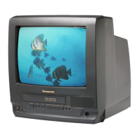
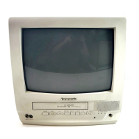
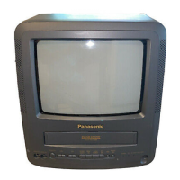
Panasonic QUASAR PV-C1350W

Panasonic QUASAR PV-C1350W
187 pages
To Next Page IconTo Next Page
Loading...
ORDER NO. MKE0001100C1
B3
Combination VCR
PVQ-1310 / PV-C1320 / PV-C1330W / VV-1300 / VV-1310W /
PV-C1340 / PV-C1350W / PV-C2010 / PV-C2020 / PV-C2030W
/ VV-2000 / PV-C2060
SPECIFICATIONS
1
Question and Answer IconNeed help?

Do you have a question about the Panasonic QUASAR PV-C1350W and is the answer not in the manual?

Panasonic QUASAR PV-C1350W Specifications

General IconGeneral
BrandPanasonic
ModelQUASAR PV-C1350W
CategoryTV VCR Combo
Screen Size13 inches
Screen TypeCRT
VCR TypeVHS
TunerNTSC
Audio OutputMono
InputsComposite Video, RF
OutputsComposite Video
Power Supply120V AC, 60Hz

Summary

1. SAFETY PRECAUTIONS

General Safety Guidelines

Essential safety measures and precautions for servicing.

5. SERVICE NOTES

Simplified Fault Finding Data

Using the diagnostic system for fault code identification.

5.1.6. Memory IC Initialization

5.1.8. Jammed Tape Removal Methods

Manual Methods for Jammed Tape Removal

Step-by-step guides to remove a jammed tape manually or electrically.

6. DisassemblyAssembly Procedures

6.1.1. Disassembly Flowchart (Cabinet Section)

Visual flowchart for disassembling the cabinet section.

6.2. Mechanism Section

6.2.1. DisassemblyReassembly Method

Procedures for disassembling and reassembling the mechanism.

7. Adjustment Procedures

7.2. Mechanical Adjustments

Procedures for mechanical adjustments like cleaning and alignment.

7.2.2.1. Back Tension Confirmation

7.2.2.2. MR Head Gap Adjustment

7.3. Electrical Adjustment

7.3.1. Test Equipment Required

List of test equipment needed for electrical adjustments.

7.3.3. 115 V Adjustment

7.3.10. Focus, Screen, Cut Off, Drive Adjustment

7.3.12. Purity Adjustment

7.3.13. Static Central Convergence Adjustment

8. Schematic Diagrams

Main V (Power Supply) Schematic Diagram

Schematic diagram for the power supply section.

9. Circuit Board Layouts

TVVCR Main C.B.A. Layout

Layout of components on the TV/VCR Main Circuit Board Assembly.

10. Block Diagrams

Power Supply Block Diagram

Block diagram illustrating the power supply circuit.

11. Exploded Views

11.1. Mechanism (Top) Section Exploded View

Exploded view of the top section of the mechanism.

12. Replacement Parts Lists

12.2. Mechanical Replacement Parts List

List of mechanical parts used in the mechanism section.

12.3. Electrical Replacement Parts List

List of parts for printed circuit boards (C.B.A.s).

180. TVVCR Main C.B.A. Waveform Diagrams

Related product manuals