EasyManua.ls Logo

Panasonic RF-3100

Panasonic RF-3100
32 pages
To Next Page IconTo Next Page
Loading...

Other manuals for Panasonic RF-3100

Question and Answer IconNeed help?

Do you have a question about the Panasonic RF-3100 and is the answer not in the manual?

Panasonic RF-3100 Specifications

General IconGeneral
BrandPanasonic
ModelRF-3100
CategoryRadio
LanguageEnglish

Summary

Service Manual Specifications

Location of Controls and Components

Control and Indicator Identification

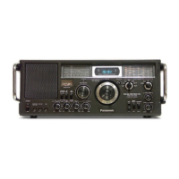
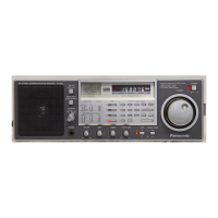
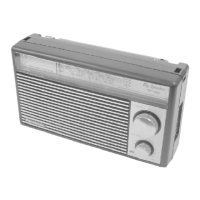
Identifies all external controls, switches, indicators, and ports on the radio.

Alignment and Adjustment Instructions

General Alignment Precautions

Outlines essential notes and settings before performing alignment.

MW and AM-IF Alignment

Details the specific procedures for aligning MW and AM-IF sections.

SW VFO and VCO Alignment

Describes the alignment process for SW VFO and VCO circuits.

SW, FM, and PLL Alignment Procedures

SW 2 nd Local OSC Alignment

Provides steps for aligning the SW 2nd local oscillator circuit.

BFO, Tuning Meter, and FM Alignment

Covers alignment for BFO, tuning meter, and FM bands.

Advanced Alignment and PLL Checks

2 nd Local Filter Alignment

Details the adjustment procedure for the 2nd local filter.

PLL and Counter Block Alignment

Covers adjustments for PLL and counter blocks.

VFO Mix Out Alignment

Describes alignment for VFO mix out frequencies.

Alignment Point Diagrams

Test Point Locations for Alignment

Illustrates specific test points on circuit boards for alignment procedures.

Component Identification and Alignment Notes

Alignment Measurement Notes

Provides important notes for DC voltage measurements and settings.

Schematic Diagram - Counter Section

Counter Circuit Schematic

Illustrates the schematic diagram of the counter circuitry.

Schematic Diagrams - RF and Control

RF, Regulator, and Oscillator Schematics

Shows schematics for RF, power regulator, and oscillator circuits.

Switch Position Settings

S501 Switch Configurations

Details the operational states of the band selector switches S501-1 and S501-2.

Wiring and Connection Diagrams

Power Supply Wiring

Illustrates the wiring diagram for the power supply circuit.

Power Supply and Filter Circuits

Schematic Diagram - RadioAudio

RadioAudio Schematic Details

Circuit Board Voltage Measurements

Circuit Board Schematic and Voltage Data

IC and Transistor Voltage Data

Electrical Parts Location Diagrams

Replacement Parts List - ICs, Transistors, Diodes

Replacement Parts List - Coils, Resistors, Filters

Replacement Parts List - Resistors

Replacement Parts List - Capacitors

Replacement Parts List - Capacitors, Cabinets, Electrical

Related product manuals