8
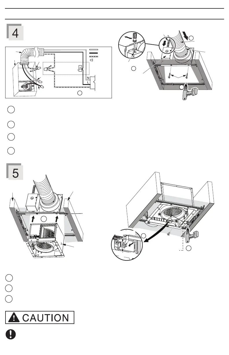
Refer to WIRING DIAGRAM (Page 5). Follow all the local electrical safety codes as well as the National Electrical
Code (NEC). Use UL approved wire nuts to connect fan wires. After connecting wires, replace junction box cover.
3
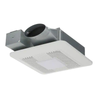
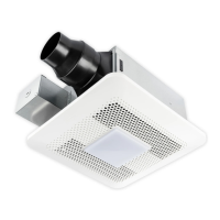
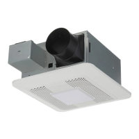
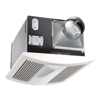
Install and secure fan body
2 self-drilling
screws
Plug connector
Receptacle
Insert fan body and slide into adaptor assembly until the flange overlaps the Flex-Z Fast™ bracket.
1
2
3
Secure the fan body to Flex-Z Fast™ bracket by using 2 self-drilling screws.
Plug connector into receptacle and secure fan body to adaptor by using machine screw (M4X8).
Please take care when installing the machine screw (Step 5) to avoid cross threading and to ensure that the
screw does not strip or come in contact with Flex-Z Fast™ bracket.
2
3
Insert circular exhaust duct
1
2
4
Remove screw from junction box cover to remove the knock-out hole and secure conduit or stress relief to junction
box knock-out hole.
Install the circular exhaust duct and secure it with clamps or ties and seal it with mastic or approved foil tape. A 4
inch circular duct is needed to connect to the relevant part of the adaptor.
Install the adaptor to Flex-Z Fast™ bracket by using 2 self-drilling screws.
Machine screw
(M4X8)
INSTALLATION (RETROFIT) (CONTINUED)
3
Earth ground
Earth ground
Conduit
Junction
box
Neutral
Live
AC 120 V
60 Hz
LINE IN
Switch box
Wire nuts
GREEN
BLACK
WHITE
2 Self-drilling screws
Mastic or
approved
foil tape
Circular exhaust
duct
Junction box
cover
Knock-out
hole
Conduit
4
1
2
2 Self-drilling screws
1
Fan body
Joist
Joist
Flex-Z Fast™
bracket