EasyManua.ls Logo

Panasonic RQ-P303 User Manual

Panasonic RQ-P303
13 pages
To Next Page IconTo Next Page
Page #1 background imageLoading...
Page #1 background image
wine
'
z
i
:
Hi
cnet
enna
me
mim
SERS
Seances
arent
rank
Po
ohne
ete
tacsccteincth
pparonar
eesti
ne
y
|
i
|
E
i
i
i
2
|
i
|
/
H
|
:
{
|
I
i
i
i
i]
t
i
§
i
i
|
i
_porennmninenoattnntnnentarrme
crete
re)
®
>
&
au
®
ri
@
Y)
a
©
at
ee
st
e
2
i
4
v4
Yaad
es
Sao
ot
ea
ttl
J
J
rc
a
aaa
§
|
©
are
a
@
ae
Ty
ee
AL.
Lb.
wey
OD
ee
rn
nnn
en
OoUm
69
bal
*
ed
£
en.
«
sam
fal
“ud,
my
Nit
ead
|
4
a
AL
tony
y
A
4
Question and Answer IconNeed help?

Do you have a question about the Panasonic RQ-P303 and is the answer not in the manual?

Panasonic RQ-P303 Specifications

General IconGeneral
TypeCassette Player
BrandPanasonic
ModelRQ-P303
Power Supply2 x AA batteries
FeaturesAuto Reverse
Headphone JackYes
Playback Speed4.76 cm/s
Frequency Response40 Hz - 14 kHz

Summary

Product Specifications

Power, Output, and Frequency Specs

Covers power requirements, output, and frequency response.

Tape Drive and Connection Specs

Details tape speed, track system, and available jacks.

Physical Dimensions and Weight

Specifies physical size, weight, and charger info.

Control Panel Overview

Control Identification

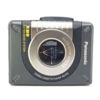
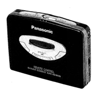
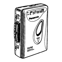
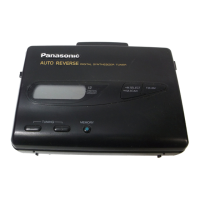
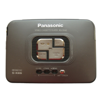
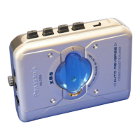
Identifies all external controls and buttons with their functions.

Battery Operation Methods

Explains rechargeable and optional battery usage.

Disassembly Procedures

Cabinet Component Removal

Steps for removing side, rear, and cassette covers.

Internal Component Removal

Procedures for removing PCB, levers, and knobs.

Component Replacement Guides

Jack Holder and PCB Replacement

Guides for replacing the jack holder and main PCB.

Cabinet and Switch Knob Replacement

Procedures for replacing rear cabinet and switch knobs.

Schematic Diagrams

Main P.C.B. Schematic Diagram

Electrical schematic for the main printed circuit board.

Head P.C.B. Schematic Diagram

Electrical schematic for the head printed circuit board.

Circuit Board Layouts

Main P.C.B. Wiring Diagram

Detailed wiring and component placement for the main PCB.

Head P.C.B. Wiring Diagram

Detailed wiring and component placement for the head PCB.

Measurement and Adjustment

Adjustment Instructions

Steps for performing device adjustments.

Tape Speed and Mechanism Checks

Procedures for tape speed adjustment and mechanism operation.

Tape Pass Control System

Explanation of the Tape Pass Control system.

IC Terminal Functions

IC1 AN6611ST2 Terminal Details

Pinout and function description for IC1.

Component Identification

Component Listings and Safety Notes

Lists resistors, capacitors, transistors, diodes, and safety components.

Integrated Circuit and Variable Resistors

Details ICs, variable resistors, switches, and jacks.

Parts Location and Lists

Mechanism and Cabinet Parts Locations

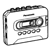
Visual guides for mechanism and cabinet parts.

Mechanism and Accessories Lists

Detailed lists of mechanism parts and accessories.

Related product manuals