iX
—— CONTENTS ——
Section 1. SPECIFICATIONS ..........................................................................................
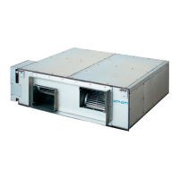
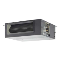
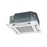
1-1. Unit Specifications .......................................................................................................
1-2. Major Component Specifications ................................................................................
1-3. Other Component Specifications ................................................................................
1-4. Dimensional Data ................................................................................................................
1-5. Refrigerant Flow Diagram ..................................................................................................
1-6. Operating Range .................................................................................................................
1-1-1-1-1
1-1-1-3-1
1-4-1
1-5-1
1-6-1
1-7-1
1-8-1
1-11-1-1-1
1-12-1
1-1-1-2-1
1-1-1-1-2
1-7. Capacity Correction Graph According to Temperature Condition ................................
1-8. Noise Criterion Curves .......................................................................................................
1-9-1
1-10-1
1-9. Indoor Fan Performance ....................................................................................................
1-10. ELECTRICAL WIRING ....................................................................................................
1-11. Installation Instructions ..........................................................................................
1-12. Capacity Table ................................................................................................................
2-1
3-1
3-2
3-4
Section 2. TEST RUN .................................................................................................................
Section 3. ELECTRICAL DATA ...............................................................................................
3-2. Indoor Units (Electric Wiring Diagram) ................................................................................
3-1. Outdoor Units (Electric Wiring Diagram) ..............................................................................
4-1
4-2
4-10
Section 4. PROCESS AND FUNCTIONS................................................................................
4-2. Outdoor Unit Control PCB (ACXA73-2859*, ACXA73-3030*, ACXA73-3028*)..................
4-1. Control Functions ...................................................................................................................
5-1
5-2
5-4
Section 5. TROUBLE DIAGNOSIS..........................................................................................
5-5
5-32
5-33
5-34
5-35
5-36
5-37
5-1. Contents of Remote Controller Switch Alarm Display ......................................................
5-2. Outdoor Unit Control Panel LED Display ............................................................................
5-3. PAC System Alarm Codes ....................................................................................................
5-4. Inspection of Parts (Outdoor Unit) .....................................................................................
5-5. Symptom: Thermostat in OFF continues or cycles OFF & ON too frequently...............
5-6. Table of Thermistor Characteristics ..................................................................................
5-7. How to Remove the Compressor .......................................................................................
5-8. How to Remove the Electrical Component Box ...............................................................
5-9. Symptom: Thermostat in OFF continues or cycles OFF & ON too frequently...............
6-1
6-2
6-2
Section 6. OUTDOOR UNIT MAINTENANCE REMOTE CONTROLLER...............................
6-3
6-8
6-10
6-11
6-1. Overview ................................................................................................................................
6-2. Functions ................................................................................................................................
6-3. Normal Display Operations and Functions .........................................................................
6-4.
Monitoring Operations: Display of Indoor Unit and Outdoor Unit Sensor Temperatures
....
6-5. Monitoring the Outdoor Unit Alarm History: Display of Outdoor Unit Alarm History....
6-6. Settings Modes: Setting the Outdoor Unit EEPROM .......................................................
4-184-3. Outdoor Unit HIC Board (ACXA73-2760*, ACXA73-3104*)................................................
4-204-4. Indoor Unit Control PCB Switches and Functions............................................................
2-9. Test Run Procedure ............................................................................................................
2-2
2-3
2-4
2-4
2-6
2-8
2-5
2-5
2-14
2-14
2-15
2-14
2-1. Preparing for Test Run .........................................................................................................
2-2. Precautions ............................................................................................................................
2-3. Caution ...................................................................................................................................
2-4. Test Run Procedure ..............................................................................................................
2-5. Items to Check Before the Test Run ...................................................................................
2-6. Test Run Using the Remote Controller ...............................................................................
2-7. Contents of Remote Controller Switch Alarm Display ......................................................
2-8. System Control ......................................................................................................................
2-10. CHECKS AFTER INSTALLATION HAVE COMPLETED ..................................................
2-11. REGARDING DELIVERY TO THE CUSTOMER ................................................................
2-12. Caution for Pump Down ...................................................................................................
SM830277-00_大洋州向け R32シングル_TD&SM.indb 10 19/02/26 9:34:28
 Loading...