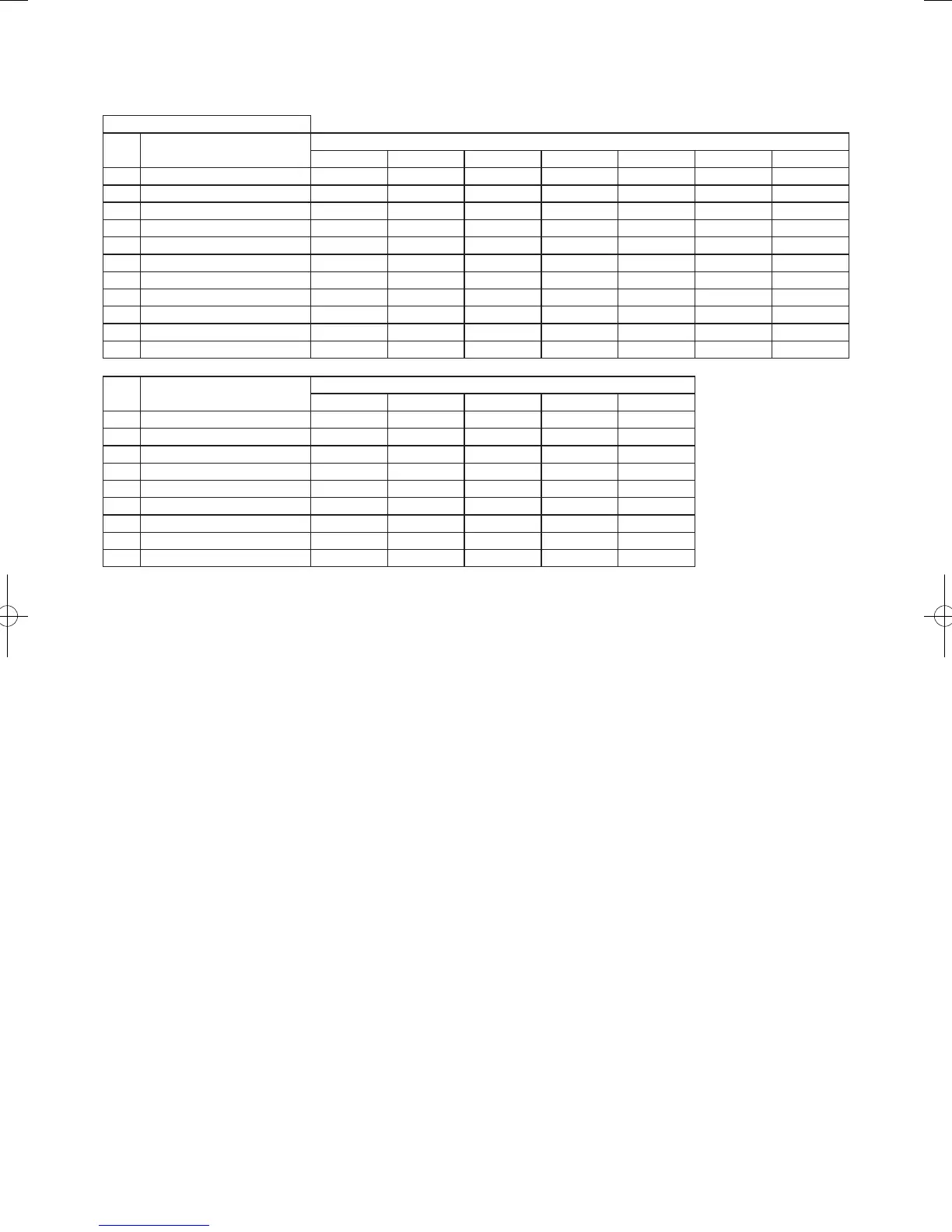
Model No.
i
• To be connecting Indoor Unit
Indoor Units
Type Indoor Unit Type
Rated Capacity
15 22 28 36 45 56 60
D1 1-Way Cassette
S-28MD1E5 S-36MD1E5 S-45MD1E5 S-56MD1E5
L1 2-Way Cassette
S-22ML1E5 S-28ML1E5 S-36ML1E5 S-45ML1E5 S-56ML1E5
U2 4-Way Cassette
S-22MU2E5A S-28MU2E5A S-36MU2E5A S-45MU2E5A S-56MU2E5A S-60MU2E5A
Y2 4-Way Cassette 60 × 60
S-15MY2E5A S-22MY2E5A S-28MY2E5A S-36MY2E5A S-45MY2E5A S-56MY2E5A
K1 Wall-Mounted
S-45MK1E5A S-56MK1E5A
K2 Wall-Mounted
S-15MK2E5A S-22MK2E5A S-28MK2E5A S-36MK2E5A S-45MK2E5A S-56MK2E5A
T2 Ceiling
S-36MT2E5A S-45MT2E5A S-56MT2E5A
F2 Low Silhouette Ducted
S-15MF2E5A S-22MF2E5A S-28MF2E5A S-36MF2E5A S-45MF2E5A S-56MF2E5A S-60MF2E5A
M1 Slim Low Static Ducted
S-15MM1E5A S-22MM1E5A S-28MM1E5A S-36MM1E5A S-45MM1E5A S-56MM1E5A
P1 Floor Standing
S-22MP1E5 S-28MP1E5 S-36MP1E5 S-45MP1E5 S-56MP1E5
R1 Concealed Floor Standing
S-22MR1E5 S-28MR1E5 S-36MR1E5 S-45MR1E5 S-56MR1E5
Type Indoor Unit Type
Rated Capacity
71 / 73 90 106 140 160
D1 1-Way Cassette
S-73MD1E5
L1 2-Way Cassette
S-73ML1E5
U2 4-Way Cassette
S-73MU2E5A S-90MU2E5A S-106MU2E5A S-140MU2E5A S-160MU2E5A
K1 Wall-Mounted
S-73MK1E5A S-106MK1E5A
K2 Wall-Mounted
S-73MK2E5A S-106MK2E5A
T2 Ceiling
S-73MT2E5A S-106MT2E5A S-140MT2E5A
F2 Low Silhouette Ducted
S-73MF2E5A S-90MF2E5A S-106MF2E5A S-140MF2E5A S-160MF2E5A
P1 Floor Standing
S-71MP1E5
R1 Concealed Floor Standing
S-71MR1E5
IMPORTANT!
Please Read Before Starting
This air conditioner must be installed by the sales dealer
or installer.
This information is provided for use only by authorized
persons.
For safe installation and trouble-free operation, you
must:
●
Carefully read this instruction booklet before beginning.
●
Follow each installation or repair step exactly as shown.
●
This air conditioner shall be installed in accordance with
National Wiring Regulations.
●
This product is intended for professional use.
Permission from the power supplier is required when
installing the U-4LE2E8, U-5LE2E8, U-6LE2E8 outdoor
units that are connected to a 16 A distribution network.
●
This equipment complies with EN/IEC 61000-3-12
provided that the short-circuit power Ssc is greater than
or equal to the following table at the interface point
between the user’s supply and the public system.
It is the responsibility of the installer or user of
the equipment to ensure, by consultation with the
distribution network operator if necessary, that the
equipment is connected only to supply with a short-
circuit power Ssc greater than or equal to the values in
the table.
U-4LE2E5 U-5LE2E5 U-6LE2E5
Ssc 3,000 kVA 4,550 kVA 4,750 kVA
●
The product meets the technical requirements of
EN/IEC 61000-3-3.
●
Pay close attention to all warning and caution notices
given in this manual.
WARNING
This symbol refers to a hazard or unsafe
practice which can result in severe
personal injury or death.
CAUTION
This symbol refers to a hazard or unsafe
practice which can result in personal
injury or product or property damage.
If Necessary, Get Help
These instructions are all you need for most installation
sites and maintenance conditions. If you require help for
a special problem, contact our sales/service outlet or your
certified dealer for additional instructions.
In Case of Improper Installation
The manufacturer shall in no way be responsible for
improper installation or maintenance service, including
failure to follow the instructions in this document.
SPECIAL PRECAUTIONS
WARNING
Risk of Electric Shock
ELECTRICAL SHOCK CAN
CAUSE SEVERE PERSONAL
INJURY OR DEATH. ONLY A
QUALIFIED, EXPERIENCED
ELECTRICIAN SHOULD
ATTEMPT TO WIRE THIS
SYSTEM.
• Do not supply power to the unit until
all wiring and tubing are completed or
reconnected and checked.
• Highly dangerous electrical voltages are
used in this system. Carefully refer to the
wiring diagram and these instructions
when wiring. Improper connections
and inadequate grounding can cause
accidental injury or death.
• Connect all wiring tightly. Loose wiring
may cause overheating at connection
points and a possible fire hazard.
• Provide a power outlet to be used
exclusively for each unit.
• ELCB must be incorporated in the
fixed wiring. Circuit breaker must be
incorporated in the fixed wiring in
accordance with the wiring regulations.
U-4LE2E5 U-5LE2E5 U-6LE2E5
Circuit breaker
25 A 30 A 35 A
U-4LE2E8 U-5LE2E8 U-6LE2E8
Circuit breaker
15 A 15 A 15 A
• Provide a power outlet exclusively for
each unit, and full disconnection means
having a contact separation by 3 mm
in all poles must be incorporated in the
fixed wiring in accordance with the wiring
rules.
• To prevent possible hazards from
insulation failure, the unit must be
grounded.
• This equipment is strongly recommended
to be installed with Earth Leakage
Circuit Breaker (ELCB) or Residual
Current Device (RCD). Otherwise, it may
cause electrical shock and fire in case
of equipment breakdown or insulation
breakdown.
00_300313_2WAY_Eng.indb 2 2017/12/14 13:47:28
SM830258-01_欧州向け_1fan_mini_VRF.indb 2 18/03/02 10:16:58
 Loading...


