5 - 23
3. Remote Controller Servicing Functions
5
VRF SYSTEMS Indoor Unit
The procedure below displays the sensor
temperatures from the remote controller, indoor unit,
and outdoor unit on the remote controller.
<Procedure to CZ-RTC2>
1
Press and hold the and buttons
simultaneously for 4 seconds or longer.
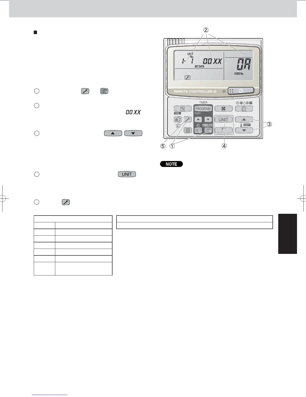
2
The unit No. “X-X” (main unit No.), item code “XX”
(sensor address), and servicing monitor “ ”
(sensor temperature) are displayed on the remote
controller LCD display. (See Fig. 12 at right.)
3
Press the temperature setting /
buttons and select the item code to the address of
the sensor to monitor.
(For the relationships between the sensor
addresses and sensor types, refer to the table of
temperature sensors and addresses at below.)
4
If group control is in effect, press the
button to select the unit to monitor.
Press the temperature setting buttons to select the
item code to change.
5
Press the button to return to normal remote
controller display.
Sensor Temperature Display Function
(displayed regardless of whether unit
is operating or stopped)
CZ-RTC2
The temperature display appears as “- - - -” for units
that are not connected.
If monitor mode is engaged while normal operation
is in progress, only the parts of the LCD display
shown in the figure will change. Other parts
continue to display the same information as during
normal operation.
*
* Refer to the Service Manual of Outdoor Unit.
Fig. 12
Indoor unit sensors Outdoor unit sensors
02 Intake temp.
03 E1
04 E2
05 E3
06 Discharge temp.
07 Discharge temp. setting
08
Position of indoor unit
electronic control valve
SM830232-00欧州向けVRFIndoor201404.indb23SM830232-00欧州向けVRFIndoor201404.indb23 2014/04/2511:11:162014/04/2511:11:16
 Loading...


