1
1-352
Automatic Address Setting
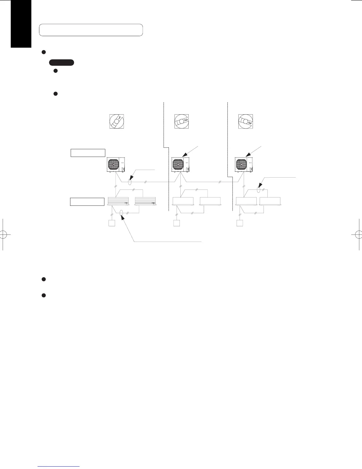
Basic wiring diagram
(1) Turn on the indoor and outdoor unit power for refrigerant system 1.
Short-circuit the AUTO ADD (CN041) pin.
(2) Next, turn ON the power only at the indoor and outdoor units in a different system. Short-circuit the AUTO ADD
(CN041) pin.
(3) Operation using the remote controller is now possible.
Communication for automatic address setting begins.
<Approximately 4 – 5 minutes are required.>
LED 1 and 2 on the outdoor unit control PCB blink alternately, and turn OFF when address setting is completed.
LED 1 and 2 on the outdoor unit control PCB blink alternately, and turn OFF when address setting is completed.
Repeat the same procedure for each system and complete automatic address setting.
Automatic address setting from the outdoor unit (Y1 type)
Case 1
Link wiring
If the power can be turned ON separately for the indoor and outdoor units in each system:
The indoor unit addresses can be set without running the compressor.
Be sure to use a jig for short-circuiting.
NOTE
A terminal plug (black) is attached to each of the outdoor unit control PCBs.
At only one outdoor unit, leave the terminal plug short-circuit socket on the “Yes” side.
At all the other outdoor units, change the socket (from “Yes” to “No”).
A maximum of 8 indoor units can be connected to 1 remote controller for group control.
↓
↓
↓
↓
↓
↓
3-1
3-2
1-1
1-2
2-1
2-2
Refrigerant
system No. 1
Refrigerant
system No. 2
Refrigerant
system No. 3
(Change setting to “1”)
(Change setting to “2”)
(Change setting to “3”)
Change the
terminal plug
(black) short-
circuit socket
Change the
terminal plug
(black) short-
circuit socket
Inter-unit control
wiring
Remote controller Remote controller
Inter-unit
control
wiring
No. 1
No. 2
No. 3
Remote control communication
wiring for group control
Remote controller
Indoor unit
Outdoor unit
Terminal board 1, 2
Terminal board 1, 2
System address
rotary switch on the
outdoor unit PCB
SM830211-07PAC-i.indb352SM830211-07PAC-i.indb352 2013/09/1722:48:102013/09/1722:48:10
 Loading...