1
1-399
WARNING
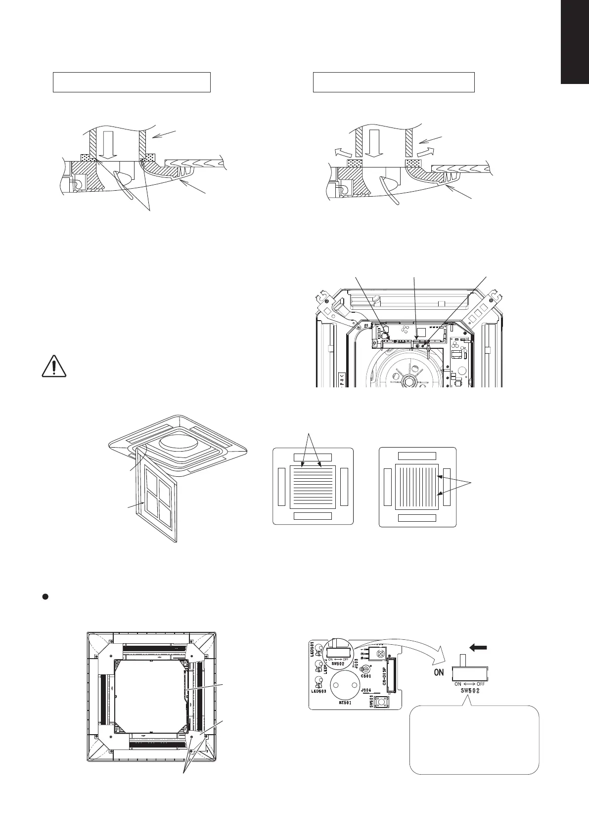
(3) Fit the decorative panel and ceiling wall together, making sure that there is no gap between the two.
Readjust indoor unit height, if there is a gap between ceiling wall and decorative panel.
(4) Open the indoor control box cover. (3 pcs. screws)
(5) Insert firmly the connector of cosmetic louver to indoor
PCB LM and WL.
Be caution not to clamp the cord in between control
board and control board cover.
(6)
When the wireless remote controller is to be used, slide the switch (SW502) on the indoor unit control PCB to the ON position.
After completing the aforementioned, install the removed
part by reversing the steps for removal.
If this setting is not made, an alarm will occur. (The operation lamp on the display blinks.)
Example of PROPER installation Example of IMPROPER installation
Air conditioner
unit
Ceiling
Decorative
panel
Fit the insulator (this part) and be
careful for cool air leakage.
Air
Fig. 1-144
Cool air
leakage
(no good)
Air conditioner
unit
Ceiling
Decorative
panel
Air
Fig. 1-145
Ground screwLM (CN033) WL (CN130)
Fig. 1-146
Be sure to hook the air inlet grille string, to prevent grille
from falling and causing injury from it.
Hang the
string
Air inlet grille
Catcher
Catcher
Fig. 1-147
6-10-3. When Using Wireless Remote Controller Instead of Wired Remote Controller
Panel cover
Remove 3 screws and panel cover
Reverse side view of Decorative Panel
Wiring
Setting status
ON:
Wireless: main, Wired: sub
OFF:
Wired: main, Wireless: sub
(at shipment)
PCB inside panel cover
Slide
SM830231-02Single欧州.indb399SM830231-02Single欧州.indb399 2014/09/1913:22:062014/09/1913:22:06

 Loading...


