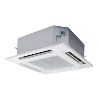
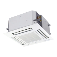
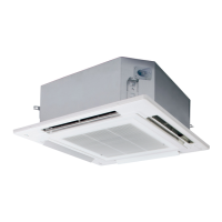
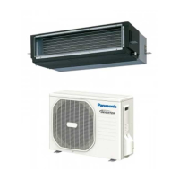
viii
Section 1. SPECIFICATIONS................................................................................................. 1-1
1-1. Unit Specifications 1-2
1-2. Dimensional Data 1-206
1-3. Refrigerant Flow Diagram 1-219
1-4. Operating Range
.................................................................................................................
..............................................................................................................
.................................................................................................
...............................................................................................................1-222
1-5. Capacity Correction Graph According to Temperature Condition ...................................... 1-223
1-6. Noise Criterion Curves 1-234
1-7. Indoor Fan Performance 1-250
1-8. Airflow Distance Chart 1-251
1-9. Intaking Fresh Air of 4-Way Cassette Type
1-10. Electrical Wiring 1-267
1-11. Installation Instructions 1-273
1-13. Capacity Table .................................................................................................................
1. Cooling Capacity Performance Data
2. Heating Capacity Performance Data
................................................................................
................................................................................
1-405
1-14. Product Fiche ................................................................................................................... 1-464
1-12. How to select AHU system ..............................................................................................1-401
1-405
1-441
1-273
......................................................................................................
....................................................................................................
......................................................................................................
1-262.......................................................................
...............................................................................................................
....................................................................................................
Outdoor Unit
Indoor Unit
.....................................................................................................................
........................................................................................................................1-342
Section 2. TEST RUN ............................................................................................................. 2-1
PRECAUTIONS REGARDING TEST RUN
CHECKS AFTER INSTALLATION HAVE COMPLETED
REGARDING DELIVERY TO THE CUSTOMER
...............................................................................
..........................................................
......................................................................
2-2
2-3
2-3
Section 3. ELECTRICAL DATA
3-1. Indoor Units (Electric Wiring Diagram, Schematic Diagram) 3-2
3-2. Outdoor Units (Electric Wiring Diagram)
...............................................
.............................................................................. 3-9
Section 4. CONTROL FUNCTIONS
..............................................................................................
.......................................................................................
3-1
4-1
4-1. Room Temperature Control
4-2. Heating Standby ....................................................................................................................
4-3. Automatic Fan Speed Control
4-4. Drain Pump Control ..............................................................................................................
4-5. Automatic Heating/Cooling Control
4-6. Automatic Flap Control .........................................................................................................
4-7. Filter Sign
4-8. Fan Control during Dry Mode
4-9. Ventilation Fan Output
4-10. T10 Terminal ........................................................................................................................
4-11. Parameter
4-12. Outdoor Units Control PCB
4-13. Functions of Outdoor Unit PCB
4-14. Self-Diagnostics Function Table
...................................................................................................
...............................................................................................
.......................................................................................
..............................................................................................................................
................................................................................................
...........................................................................................................
..........................................................................................................................
...............................................................................................
.........................................................................................
........................................................................................
4-2
4-4
4-5
4-6
4-7
4-8
4-8
4-9
4-9
4-9
4-10
4-11
4-19
4-22
Section 5. TROUBLE DIAGNOSIS......................................................................................... 5-1
5-1. Contents of Remote Controller Switch Alarm Display
5-2. Outdoor Unit Control Panel LED Display
5-3. PAC System Alarm Codes 5-5
5-4. Inspection of Parts (Outdoor Unit) 5-68
5-5. Symptom: Thermostat in OFF continues or cycles OFF & ON too frequently
5-2
5-69
5-6. How to Clean Heat Exchanger
...........................................................
............................................................................... 5-4
.....................................................................................................
.......................................................................................
.....................
............................................................................................ 5-70
5-7. How to Replace Fan Motor ................................................................................................. 5-71
—— CONTENTS ——
SM830231-02Single欧州.indbSec1:viiiSM830231-02Single欧州.indbSec1:viii 2014/09/1117:38:532014/09/1117:38:53

 Loading...
