7
ENGLISH
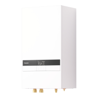
Terminal screw Tightening torque cN•m {kgf•cm}
M4 157~196 {16~20}
M5 196~245 {20~25}
*1 - Earth wire must be longer than other cables for safety reasons
Power Supply Cord
Holder
(Clamper)
Terminal Board
RCCB/ELCB
*1
*1
Connecting Cable
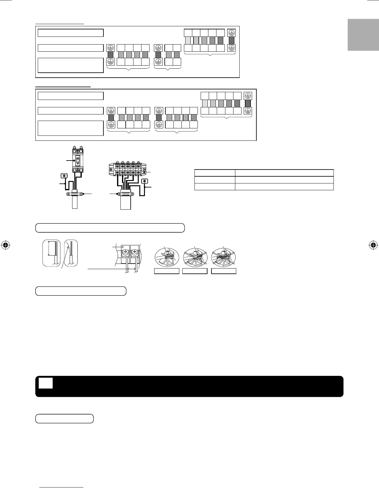
Wire stripping
5mm or
more
(gap between
wires)
No loose strand
when insert
Indoor/outdoor
connecting
terminal board
10 ± 1mm
ACCEPT PROHIBITED
Conductor
over insert
Conductor not
fully insert
Conductor
fully insert
PROHIBITED
WIRE STRIPPING AND CONNECTING REQUIREMENT
CONNECTING REQUIREMENT
For S*C09*3E8
•
The equipment’s Power Supply 1 complies with IEC/EN 61000-3-2.
•
The equipment’s Power Supply 1 complies with IEC/EN 61000-3-3 and can be connected to current supply network.
•
The equipment’s Power Supply 2 complies with IEC/EN 61000-3-2.
•
The equipment’s Power Supply 2 complies with IEC/EN 61000-3-11 and shall be connected to suitable supply network, with the following
maximum permissible system impedance Z
max
= 0.426 at the interface. Please liaise with supply authority to ensure that the Power Supply
2 is connected only to a supply of that impedance or less.
For S*C12*9E8/S*C16*9E8
•
The equipment’s Power Supply 1 complies with IEC/EN 61000-3-2.
•
The equipment’s Power Supply 1 complies with IEC/EN 61000-3-3 and can be connected to current supply network.
•
The equipment’s Power Supply 2 complies with IEC/EN 61000-3-2.
•
The equipment’s Power Supply 2 complies with IEC/EN 61000-3-3 and can be connected to current supply network.
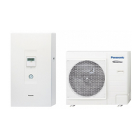
For model S*C09*3E8
Terminal on the outdoor unit 1 2345
Colour of wires (Connecting cables)
Terminal on the indoor unit L
A1
L
A2
L
A3
N LN 12345
(Power Supply Cord)
Terminals on the isolating device
from power supply (Disconnecting
means)
L
A1
L
A2
L
A3
N LN
Indoor unit/Outdoor unit
connection
Power Supply 1
Main Power Supply
or Main + Backup
Heater Power Supply
Booster Heater
Power Supply
Power Supply 2
For model S*C12/16*9E8
Terminal on the outdoor unit 1 2345
Colour of wires (Connecting cables)
Terminal on the indoor unit L
A1
L
A2
L
A3
N L
B1
L
B2
L
B3
N 12345
(Power Supply Cord)
Terminals on the isolating device
from power supply (Disconnecting
means)
L
A1
L
A2
L
A3
N L
B1
L
B2
L
B3
N
Power Supply 1 Power Supply 2
Indoor unit/Outdoor unit
connection
Main Power Supply
Booster + Backup
Heater Power Supply
INSTALLATION OF REMOTE CONTROLLER AS ROOM
THERMOSTAT
7
•
Remote Controller 3 mounted to the Indoor Unit can be moved to the room and serve as Room Thermostat.
Installation Location
•
Install at the height of 1 to 1.5 m from the fl oor (Location where average room temperature can be detected).
•
Install vertically against the wall.
•
Avoid the following locations for installation.
1. By the window, etc. exposed to direct sunlight or direct air.
2. In the shadow or backside of objects deviated from the room airfl ow.
3. Location where condensation occurs (The Remote Controller is not moisture proof or drip proof.)
4. Location near heat source.
5. Uneven surface.
•
Keep distance of 1 m or more from the TV, radio and PC. (Cause of fuzzy image or noise)
ACXF60-03130_EN ES IT.indb 7ACXF60-03130_EN ES IT.indb 7 9/22/2016 4:21:27 PM9/22/2016 4:21:27 PM
 Loading...