EasyManua.ls Logo

Panasonic SA-AK66 - Service Manual

Panasonic SA-AK66
79 pages
Print Icon
To Next Page IconTo Next Page
Loading...
ORDER
NO.
MD0102038C1
Service
Manual
COMPACT
DIGITAL
AUDIO
i
Remote
Control
Transmitter
S8-AKGG
Specifications
@
AMPLIFIER
SECTION
Power
output
THD
10%
Total
harmonic
distortion
(Front
1
kHz)
(Center
1
kHz)
(Surround
1
kHz)
Total
output
in
stereo
mode
Total
output
in
Dolby
Pro
Logic
mode
FTC
Power
output
THD
10%
Total
harmonic
distortion
(Front
70-16
KHz)
(Center
70-16
kHz)
(Surround
70-16
kHz)
Total
output
in
stereo
mode
Total
output
in
Dolby
Pro
Logic
mode
Input
sensitivity
AUX
Input
Impedance
AUX
@
FM
TUNER
SECTION
Frequency
range
Sensitivity
SA-AKE6
SB-AKSS6
70
W
per
channel
(6
Q)
70
W
per
channel
(8
Q)
35
W
per
channel
(8
Q)
140
W
280
W
60
W
per
channel
(6
Q)
70
W
per
channel
(8
Q)
35
W
per
channel
(8
Q)
120
W
260
W
250
mV
13
kQ
87.9
-
107.9
MHz
(200
kHz
steps)
87.5
-
108.0
MHz
(100
kHz
steps)
2.5
pV
(IHF)
Panasonic
CD
Stereo
System
SA-AK66
Colour
(S)...
Silver
Type
Area
(P)...
U.S.A.
(PC)...
Canada
TAPE
SECTION
:
SG-2W
MECHANISM
SERIES
CD
SECTION
:
RAE0152Z-3
TRAVERSE
DECK
SERIES
S/N
26
dB
Antenna
terminal(s)
@
AM
TUNER
SECTION
Frequency
range
Sensitivity
S/N
20
dB
(at
1000
kHz)
@
CASSETTE
DECK
SECTION
Track
system
2.2
UV
75
Q
(unbalanced)
520
-
1710
kHz
(10
kHz
steps)
560
pV/m
4
track,
2
channel
Heads
Record/playback
Solid
permalloy
head
Erasure
Double
gap
ferrite
head
Motor
DC
servo
motor
AC
bias
100
kHz
AC
erase
100
kHz
Recording
system
Erasing
system
Tape
speed
4.8
cm/s
Frequency
response
(+3
dB,
-6
dB
at
DECK
OUT)
NORMAL
(TYPE
1)
35
Hz
-
14
kHz
S/N
Wow
and
flutter
50
dB
(A
weighted)
0.18
%
(WRMS)
Fast
forward
and
rewind
time
Approx.
120
seconds
with
C-60
cassette
tape
m@
CD
SECTION
Sampling
frequency
44.1
kHz
Decoding
16
bit
linear
©
2001
Matsushita
Electronics
(S)
Pte.
Ltd.
All
rights
reserved.
Unauthorized
copying
and
distribution
is
a
violation
of
law.
Question and Answer IconNeed help?

Do you have a question about the Panasonic SA-AK66 and is the answer not in the manual?

Summary

Specifications

Amplifier Section

Details power output and harmonic distortion specifications.

Tuner Sections (AM;FM)

Covers frequency range and sensitivity for AM and FM tuning.

Cassette Deck Section

Specifies track system, heads, tape speed, and frequency response.

CD Section

Lists sampling frequency and decoding format for the CD section.

Safety and Initial Procedures

Safety Precautions

General safety guidelines for servicing the unit.

Pre-Repair Procedures

Procedures and precautions before commencing repair or adjustment.

Protection Circuitry

Explains the unit's protection circuitry and how it functions.

Included Accessories

Traverse Deck Handling Precautions

Electrostatic Discharge Prevention

Methods for grounding to prevent electrostatic discharge damage.

Laser Diode Safety Precautions

Operation Procedures

Front Panel Controls (Main Unit)

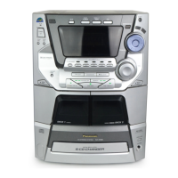
Identification and function of controls on the main unit's front panel.

Center Console Controls

Identification and function of controls on the center console.

Remote Control Operations

Service Procedures Overview

Servicing Jig Information

Information about a special gear used for servicing the unit.

PCB Checking Procedures

Procedures for checking major printed circuit boards.

PCB Disassembly Procedures

Main, Transformer, Panel, and Deck PCB Disassembly

Detailed steps for disassembling the main, transformer, panel, and deck PCBs.

Component Replacement Procedures

Traverse Deck Replacement

Step-by-step guide for replacing the traverse deck unit.

CD Servo PCB Installation

Instructions for installing the CD servo PCB after replacement.

Power Amplifier IC Replacement

Traverse Unit Disassembly and Assembly

Traverse Unit Handling

Detailed steps for disassembling and reassembling the traverse unit.

Traverse Unit Replacement

Procedures for removing and installing the traverse unit.

Disc Tray Disassembly and Assembly

Self-Diagnostic Functions

Self-Diagnostic Display Information

Information on the self-diagnostic display function.

Entering Self-Diagnostic Mode

Step-by-step instructions to access the self-diagnostic mode.

Cassette Mechanism Test Procedure

Procedure for testing the cassette mechanism and error codes.

Error Code Descriptions

Cassette Mechanism Errors

Lists error codes and their corresponding problem conditions for the cassette mechanism.

CD;Changer Errors

Lists error codes for CD/Changer issues and their problems.

Power Supply Errors

Details error codes related to power supply abnormalities.

CD Test Mode Operations

Setting CD Test Mode

Instructions on how to activate the CD test mode.

Interpreting CD Auto-Adjustment Results

How to interpret the results of CD automatic adjustment.

Measurements and Adjustments

Cassette Deck Measurements & Adjustments

Measurement conditions and adjustments for the cassette deck.

Tape Speed Adjustment (Deck 1;2)

Procedure for adjusting tape speed on both decks.

Bias and Erase Voltage Check

Steps to check bias and erase voltage for the cassette deck.

Bias Frequency Adjustment (Deck 1;2)

How to adjust bias frequency for the cassette decks.

Tuner Section AM-IF Alignment

Alignment procedure for the AM Intermediate Frequency (IF) stage.

Alignment Points

Cassette Deck Alignment Points

Specific points for alignment in the cassette deck section.

Tuner Section Alignment Points

Alignment procedures and points for the tuner section.

Component Illustrations

IC Terminal Functions

IC701 Servo Amplifier Pin Functions

Pin assignments and functions for the servo amplifier IC.

IC702 Processor Pin Functions

Pin functions for the servo processor and digital signal processing IC.

IC Terminal Functions (Continued)

IC703 Motor Driver Pin Functions

Pin functions for IC703, which drives coils and motors.

IC Terminal Functions (Continued)

IC600 Microprocessor Pin Functions

Pin assignments and functions for the system microprocessor IC.

System Block Diagram

Schematic Diagram Notes and Cautions

Schematic Diagram Notes

Notes on schematic diagram interpretation and safety.

Safety Notices

Safety notice regarding component identification and replacement.

Static Sensitivity Precautions

Precautions for handling ICs, LSIs, and VLSI due to static sensitivity.

Schematic Diagrams - CD Servo Circuit

Schematic Diagrams - CD Servo Circuit (Continued)

Schematic Diagrams - Tuner Circuit

Schematic Diagrams - Main Circuit

Schematic Diagrams - Main Circuit (Continued)

Schematic Diagrams - Main Circuit (Continued)

Schematic Diagrams - Panel Circuit

Schematic Diagrams - Panel Circuit (Continued)

Schematic Diagrams - Deck Circuit

Schematic Diagrams - Deck Circuit (Continued)

Schematic Diagrams - Power Circuit

Schematic Diagrams - Transformer Circuits

AC Transformer Circuit

Schematic for the AC transformer circuit.

Sub-Transformer Circuit

Schematic for the sub-transformer circuit.

Printed Circuit Board Layouts

CD Servo PCB Layout

Component layout for the CD servo printed circuit board.

Printed Circuit Board Layouts (Continued)

Main;Tuner PCB Layout

Component layout for the main and tuner printed circuit board.

Printed Circuit Board Layouts (Continued)

Panel PCB Layout

Component layout for the panel printed circuit board.

Printed Circuit Board Layouts (Continued)

Headphone PCB Layout

Component layout for the headphone printed circuit board.

Printed Circuit Board Layouts (Continued)

Tact Switch PCBs Layout

Component layout for the tact switch PCBs.

Printed Circuit Board Layouts (Continued)

Mechanism PCBs Layout

Component layout for the mechanism deck PCBs.

Tuner Pack PCB Layout

Component layout for the tuner pack PCB.

Printed Circuit Board Layouts (Continued)

CD Loading PCB Layout

Component layout for the CD loading PCB.

CD Detect PCB Layout

Component layout for the CD detect PCB.

Spindle Position PCB Layout

Component layout for the spindle position PCB.

Printed Circuit Board Layouts (Continued)

Deck PCB Layout

Component layout for the deck printed circuit board.

Printed Circuit Board Layouts (Continued)

Power PCB Layout

Component layout for the power printed circuit board.

Printed Circuit Board Layouts (Continued)

Transformer PCBs Layout

Component layout for the AC and sub-transformer PCBs.

Wiring Connection Diagram

Troubleshooting Guide

Parts Lists and Identification

Parts Location and Replacement List

Information on safety, part identification, and replacement.

Deck Mechanism Details

Deck Mechanism Parts Location

Exploded view showing the location of cassette deck mechanism parts.

Deck Mechanism Parts List

CD Loading Mechanism Details

CD Loading Mechanism Parts Location

Exploded view showing parts location for the CD loading mechanism.

CD Loading Mechanism Parts List

Cabinet Assembly

Cabinet Parts Location

Exploded view of cabinet parts and their locations.

Electrical Parts Lists

Printed Circuit Boards

List of printed circuit boards used in the unit.

Integrated Circuits

List of integrated circuits with their part numbers and functions.

Transistors and Diodes

Lists of transistors and diodes with part numbers and descriptions.

Switches, Connectors, Coils, and etc.

Lists of switches, connectors, coils, transformers, filters, relays, and oscillators.

Resistors List

Extensive list of resistors with part numbers and specifications.

Capacitors List

Comprehensive list of capacitors with part numbers and specifications.

Packaging Information

Packing Materials List

List of packing materials used for the product.

Accessories List

List of included accessories.

Packaging Diagram

Panasonic SA-AK66 Specifications

General IconGeneral
TypeCD Stereo System
ManufacturerPanasonic
ModelSA-AK66
CD PlayerYes
Number of Discs1
Tuner BandsFM/AM
Tape DeckYes
BluetoothNo
USB PortNo
Weight6.5 kg
Speakers2