© Panasonic Corporation 2010. All rights reserved.
Unauthorized copying and distribution is a violation
of law.
PSG1003010CE
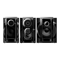
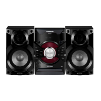
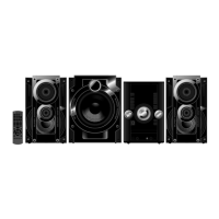
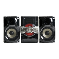
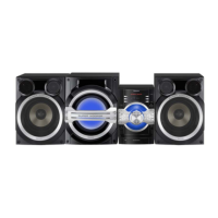
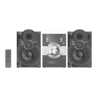
CD Stereo System
Model No. SA-AKX90PH
SA-AKX90PR
Product Color: (K)...Black Type
TABLE OF CONTENTS
PAGE PAGE
1 Safety Precautions----------------------------------------------- 4
1.1. General Guidelines---------------------------------------- 4
1.2. Before Use -------------------------------------------------- 4
1.3. Caution For Fuse Replacement------------------------ 4
1.4. Before Repair and Adjustment ------------------------- 4
1.5. Protection Circuitry---------------------------------------- 5
1.6. Safety Parts Information----------------------------------5
2Warning--------------------------------------------------------------6
2.1. Prevention of Electrostatic Discharge (ESD)
to Electrostatic Sensitive (ES) Devices---------------6
2.2. Precaution of Laser Diode -------------------------------7
2.3. Service caution based on Legal restrictions --------8
Notes: Please refer to the original service manual for:
O CD Mechanism Unit (DLS6C),Order No:MD0803034CE
O Speaker System SB-AKX90PH-K,Order No.:PSG1003001CE