Do you have a question about the Panasonic SA-AKX74PH and is the answer not in the manual?
General guidelines for safe servicing and operation.
Instructions for initial use, specifically for PH models.
Precautions before performing repairs or adjustments.
Explanation of the protection circuit and its function.
Warnings and guidelines for replacing fuses.
List of critical safety components and their importance.
Methods to prevent ESD damage to sensitive electronic components.
Safety precautions related to the laser diode in the product.
Service cautions related to lead-free solder and legal restrictions.
Specific handling precautions for the traverse unit.
Grounding procedures for preventing electrostatic damage.
General information and guidance for servicing the unit.
Information regarding compatible media formats for playback.
Explanation of buttons and their functions on the remote control.
Explanation of buttons and their functions on the main unit.
Instructions for connecting speakers and the AC power cord.
Procedure for performing a cold-start or initializing to shipping mode.
Tables detailing various modes and their operations.
Process flow for aging tests on the CD mechanism unit.
Information on entering and using the self-diagnostic mode.
Table listing error codes and their diagnostic contents.
Procedures for entering and canceling the sales demonstration lock.
Location of various parts on the circuit boards.
Troubleshooting procedures for specific error codes F61/F76.
Details on D-Amp IC operation and control signals.
Flowchart illustrating the disassembly sequence of components.
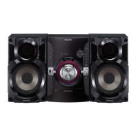
Visual guide to the location of major components and PCBs.
Step-by-step instructions for removing the top cabinet.
Step-by-step instructions for removing the front panel unit.
Step-by-step instructions for removing the microphone PCB.
Step-by-step instructions for removing the panel PCB.
Step-by-step instructions for removing the memory LED PCB.
Step-by-step instructions for removing the remote sensor PCB.
Step-by-step instructions for removing the USB PCB.
Step-by-step instructions for removing the music port PCB.
Step-by-step instructions for removing the top bar LED PCB.
Step-by-step instructions for removing the bottom bar LED PCB.
Step-by-step instructions for removing the main PCB.
Instructions for replacing the voltage regulator IC (IC2010).
Instructions for replacing the voltage regulator IC (IC2011).
Instructions for replacing the audio digital amp IC (IC5800).
Instructions for replacing the audio digital amp IC (IC5700).
Step-by-step instructions for removing the D-Amp PCB.
Instructions for replacing the audio digital amp IC (IC5900).
Step-by-step instructions for removing the SMPS PCB.
Instructions for replacing the switching regulator IC (IC5701).
Instructions for replacing the rectifier diode (D5702).
Instructions for replacing the rectifier diode (D5801).
Instructions for replacing the rectifier diode (D5802).
Instructions for replacing the regulator diode (D5803).
Step-by-step instructions for removing the CD mechanism unit.
Step-by-step instructions for removing the CD interface PCB.
Step-by-step instructions for removing the CD servo PCB.
Step-by-step instructions for removing the rear panel.
Step-by-step instructions for removing the voltage selector PCB.
Procedures for checking and repairing the main PCB.
Procedures for checking and repairing the D-Amp PCB.
Procedures for checking and repairing the panel PCB.
Procedures for checking and repairing the SMPS PCB.
Procedures for checking and repairing the CD servo PCB (Side A).
Procedures for checking and repairing the CD servo PCB (Side B).
Simplified block diagram of the power supply circuit.
Block diagram for servo and system control.
Chart detailing terminal functions for key ICs.
Block diagram illustrating the audio signal path.
Block diagram of the power supply unit.
Notes and symbols used in the schematic diagrams.
Schematic diagram of the CD servo circuit.
Schematic diagram of the main MICON circuit.
Schematic diagram of the main D-Amp circuit.
Schematic diagram of the panel circuit.
Schematics for remote sensor, USB, music port, memory LED, and bar LEDs.
Schematics for CD interface, microphone, and voltage selector circuits.
Schematic diagram of the D-Amp circuit.
Schematic diagram of the SMPS circuit.
Illustrations of the CD Servo PCB (Side A and Side B).
Illustration of the Main PCB (Side A).
Illustration of the Main PCB (Side B).
Illustrations of Panel, Remote Sensor, USB, and Music Port PCBs.
Illustrations of Memory LED, CD Interface, Top Bar LED, Bottom Bar LED, and Mic PCBs.
Illustrations of SMPS and Voltage Selector PCBs.
Illustrations of SMPS and D-Amp PCBs.
Chart of voltage and waveform values for various test points.
Voltage values for CD Servo PCB (1/3).
Voltage values for Main PCB (1/4).
Voltage values for Panel PCB.
Voltage values for D-Amp PCB.
Voltage values for SMPS PCB.
Voltage values for Mic PCB.
Table of waveforms for various test points and ICs.
Detailed terminal functions for various ICs.
Terminal functions of the Micro-Processor IC (IC2003).
Illustrations of common ICs, transistors, and diodes used in the unit.
Exploded view showing mechanical parts and their replacement list.
Location of various cabinet parts in the exploded view.
Diagram showing the packaging of the unit.
List of mechanical replacement parts with safety references.
List of electrical replacement parts with safety references.
| Type | Mini Hi-Fi System |
|---|---|
| Bluetooth | Yes |
| USB Playback/Port | Yes |
| FM Radio | Yes |
| Radio Tuner | FM |
| Number of Discs | 1 |
| Playable File Formats | MP3, WMA |
| Preset Equalizer | Yes |
| CD Player | Yes |
| Remote Control | Yes |
| Speaker Type | 2-Way |
| Dimensions (W x H x D) | 280 x 285 x 280 mm |
| Playable Media | CD, CD-R, CD-RW |