Do you have a question about the Panasonic SA-AKX74LM-K and is the answer not in the manual?
General safety rules for servicing, including leakage current checks.
Details procedures before starting repair work, like discharging capacitors.
Lists critical safety parts and emphasizes using specified replacements.
Techniques to prevent damage to sensitive components from static electricity.
Warnings and safety measures related to the product's laser diode.
Details special care needed when handling the optical pickup unit and its components.
Methods for worktable and human body grounding to prevent ESD.
Details audio output power, impedance, and distortion for the amplifier section.
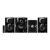
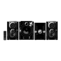
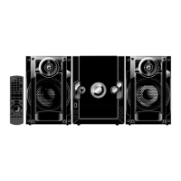
Explains the function of each button on the remote control.
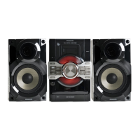
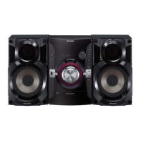
Details the function of each button on the main unit.
Procedure to initialize the unit to its shipping mode or perform a cold start.
Lists various diagnostic modes, their FL display, and key operations.
Process flow charts for aging tests of the CD mechanism unit.
Instructions for entering and exiting the self-diagnostic mode.
Lists error codes for power supply and CD mechanism issues.
Identifies key components on SMPS, Main, and D-Amp PCBs.
Checks and possible faults for "F61" or "F76" errors after power-up.
Detailed procedure for replacing the voltage regulator IC.
Detailed procedure for replacing the audio digital amp IC.
Detailed procedure for replacing the audio digital amp IC.
Detailed procedure for replacing the audio digital amp IC.
Detailed schematic of the CD servo control circuitry.
Schematic for the main microcontroller (MICON) circuit.
Schematic of the digital amplifier (D-Amp) circuit.
Detailed schematic of the D-Amp circuit, including speaker protection.
Schematic of the switching mode power supply unit.
Voltage values and waveform references for troubleshooting various circuits.
| Bluetooth | Yes |
|---|---|
| USB Playback | Yes |
| CD Player | Yes |
| FM Radio | Yes |
| Number of Discs | 1 |
| Playable File Types | MP3, WMA |
| USB Port | Yes |
| Remote Control | Yes |
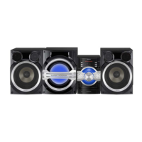
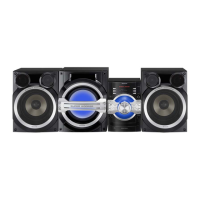
| Type | Mini Hi-Fi System |
| Speaker Type | 2-way speaker |