EasyManua.ls Logo

Panasonic SA-AKX710PU User Manual

Panasonic SA-AKX710PU
107 pages
To Next Page IconTo Next Page
Page #1 background imageLoading...
Page #1 background image
© Panasonic Corporation 2018. All rights reserved.
Unauthorized copying and distribution is a violation
of law.
PSG1804006CE
CD Stereo System
Model No. SA-AKX710PU
SA-AKX910PU
Product Color: (K)...Black Type
TABLE OF CONTENTS
PAGE PAGE
1 Safety Precautions----------------------------------------------- 3
1.1. General Guidelines---------------------------------------- 3
1.2. Before Repair and Adjustment ------------------------- 4
1.3. Protection Circuitry---------------------------------------- 4
1.4. Safety Parts Information --------------------------------- 5
2 Warning-------------------------------------------------------------- 6
2.1. Prevention of Electrostatic Discharge (ESD)
to Electrostatically Sensitive (ES) Devices---------- 6
2.2. Precaution of Laser Diode------------------------------- 6
2.3. General description about Lead Free Solder
(PbF)---------------------------------------------------------- 7
2.4. Handling Precautions for Traverse Unit-------------- 7
2.5. Grounding for electrostatic breakdown
prevention --------------------------------------------------- 8
3 Service Navigation----------------------------------------------- 9
3.1. Service Information --------------------------------------- 9
4 Specifications---------------------------------------------------- 10
5 Location of Controls and Components------------------ 11
5.1. Remote Control Key Button Operation ------------- 11
5.2. Main Unit Key Button Operation---------------------- 12
6 Service Mode----------------------------------------------------- 13
6.1. Cold-Start -------------------------------------------------- 13
6.2. Sales Demonstration Lock Function ---------------- 13
6.3. Doctor Mode Table--------------------------------------- 14
6.4. Self-Diagnostic Mode ----------------------------------- 16
6.5. Self-Diagnostic Error Code Table-------------------- 16
7 Troubleshooting Guide --------------------------------------- 18
7.1. No Power (No LED Display + No Response)----- 18
7.2. No Sound coming out from All speakers----------- 20
7.3. No Sound at USB selector Only---------------------- 22
7.4. No Sound from MIC at any selector ---------------- 24
7.5. No Sound in Tuner Mode ------------------------------ 26
Please refer to the original service manual for:
O CD Mechanism Unit, (BRS12C) Order No. PSG1303059AE
O Speaker system SB-AKX700PNK Order No. PSG1703027CE (For SA-AKX710PUK)
O Speaker system SB-AKX880PNK Order No. PSG1603003CE, SB-AKW910PUK Order No. PSG1804007CE
(For SA-AKX910PUK)
jomi

Table of Contents

Question and Answer IconNeed help?

Do you have a question about the Panasonic SA-AKX710PU and is the answer not in the manual?

Panasonic SA-AKX710PU Specifications

General IconGeneral
Number of Channels2
USB PortYes
BluetoothYes
FM RadioYes
Preset EqualizerYes
Remote ControlYes
Speaker Configuration2.0
Speaker Type2-way
Playable MediaCD
Playback FormatsMP3
Audio Input3.5mm Aux-in
Power Output1000 W

Summary

Safety Precautions and Warnings

General Safety Guidelines

Essential safety notices and general guidelines for servicing electronic equipment.

Before Repair and Adjustment Procedures

Steps to follow before commencing repair or adjustment, including capacitor discharge.

Protection Circuitry Functionality

Understanding and troubleshooting the unit's protection circuitry for safe operation.

Safety Parts Information

List of critical safety components that must be replaced with manufacturer-specified parts.

Electrostatic Discharge (ESD) Prevention

Techniques to prevent damage to sensitive electronic devices from static electricity.

Laser Diode Precautions

Safety warnings and handling precautions for the laser diode in the optical pickup unit.

Lead Free Solder (PbF) Description

General description of lead-free solder used in components and its handling during repair.

Traverse Unit Handling Precautions

Specific cautions for handling the traverse unit and optical pickup to prevent ESD damage.

Grounding for Electrostatic Prevention

Methods for grounding worktables and human bodies to prevent electrostatic discharge.

Service Navigation and Specifications

Service Information and Software Updates

Guidance on obtaining service information and managing software updates for the system.

System Specifications Overview

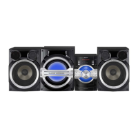
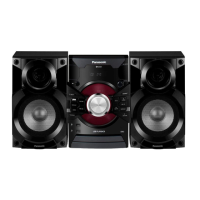
Detailed technical specifications for amplifier, tuner, disc, Bluetooth, memory, and terminal sections.

Controls and Service Modes

Remote Control Button Operations

Explanation of each button's function on the remote control for system operation.

Main Unit Button Operations

Description of each button's function on the main unit for system control.

Service Mode Functions

Procedures for entering Cold-Start and Sales Demonstration Lock modes.

Doctor Mode and Diagnostic Tables

Details on entering Doctor Mode and tables for EEPROM checksum and cold start.

Self-Diagnostic Modes and Error Codes

Information on self-diagnostic functions and tables for power supply and CD mechanism error codes.

Troubleshooting and Disassembly

Troubleshooting Guide: No Power

Flowchart for diagnosing and resolving 'No Power' issues, including check points.

Troubleshooting Guide: No Sound

Flowcharts for diagnosing and resolving 'No Sound' issues across different selectors.

Troubleshooting Guide: USB and MIC Issues

Flowcharts for diagnosing 'No Sound' from USB, MIC, and Tuner/AUX modes.

Troubleshooting Guide: Display Errors

Flowcharts for diagnosing FL display errors like 'No Play' or 'No Device' on USB.

Troubleshooting Guide: Bluetooth Pairing Failure

Procedure to diagnose and resolve Bluetooth pairing failures.

Disassembly and Assembly Instructions

General instructions and flowcharts for disassembling the unit's main components.

Component and PCB Locations

Diagrams showing the locations of main components and PCBs within the unit.

Step-by-Step Disassembly Procedures

Detailed steps for disassembling the top cabinet, front panel, and various PCBs.

System Diagrams and Measurements

System Block Diagram

Overview of the system's control, audio, and power supply block diagrams.

Wiring Connection Diagram

Diagram illustrating the wiring connections between various PCBs in the system.

Schematic Diagrams of Key Circuits

Detailed schematic diagrams for various circuits like Micon, DAMP, Tuner, and SMPS.

Printed Circuit Board Layouts

Visual layout diagrams for Main PCBs (Side A/B), Tuner, Panel, USB, Mic, and SMPS PCBs.

Voltage Measurement Points

Tables listing reference voltages for various ICs and components on the Main and SMPS PCBs.

Replacement Parts Lists

Comprehensive lists of electrical and mechanical replacement parts with their details.

Exploded Views of Cabinet Parts

Diagrams illustrating the location of cabinet parts and assembly components.

Related product manuals