EasyManua.ls Logo

Panasonic SA-AKX30PH User Manual

Panasonic SA-AKX30PH
125 pages
To Next Page IconTo Next Page
Page #1 background imageLoading...
Page #1 background image
© Panasonic Corporation 2010. All rights reserved.
Unauthorized copying and distribution is a violation
of law.
PSG1002032CE
CD Stereo System
Model No. SA-AKX30PH
SA-AKX30PN
Product Color: (K)...Black Type
TABLE OF CONTENTS
PAGE PAGE
1 Safety Precautions----------------------------------------------- 3
1.1. General Guidelines---------------------------------------- 3
1.2. Before Use (For PH only)-------------------------------- 3
1.3. Caution For Fuse Replacement------------------------ 3
1.4. Before Repair and Adjustment ------------------------- 4
1.5. Protection Circuitry---------------------------------------- 4
1.6. Safety Parts Information --------------------------------- 4
2 Warning-------------------------------------------------------------- 6
2.1. Prevention of Electrostatic Discharge (ESD)
to Electrostatic Sensitive (ES) Devices -------------- 6
2.2. Precaution of Laser Diode------------------------------- 7
2.3. Service caution based on Legal restrictions-------- 8
2.4. Handling Precautions for Traverse Unit --------------9
3 Service Navigation --------------------------------------------- 11
3.1. Service Information-------------------------------------- 11
4 Specifications---------------------------------------------------- 12
5 Location of Controls and Components------------------ 13
5.1. Main Unit Key Button Operation---------------------- 13
5.2. Remote Control Key Button Operation ------------- 14
5.3. Media Information---------------------------------------- 15
6 Self-Diagnostic and Special Mode Setting ------------- 16
6.1. Cold-Start -------------------------------------------------- 16
6.2. Doctor Mode Table--------------------------------------- 17
Notes: This model’s CD Mechanism Unit is DLS6C. Please refer to the original service manual
(Order No. MD0803034CE) for this mechanism

Table of Contents

Question and Answer IconNeed help?

Do you have a question about the Panasonic SA-AKX30PH and is the answer not in the manual?

Panasonic SA-AKX30PH Specifications

General IconGeneral
ModelSA-AKX30PH
Speaker Type2-way
Speaker Configuration2.0
Number of Discs1
CD PlayerYes
USB PortYes
USB PlaybackYes
BluetoothYes
RadioYes
FM RadioYes
Remote ControlYes
Playable MediaCD, CD-R, CD-RW
Audio InputYes
TypeMini System

Summary

Safety Precautions

General Safety Guidelines

General guidelines for servicing the equipment and handling safety.

Pre-Use and Fuse Replacement Cautions

Pre-operation checks for specific voltage settings and fuse replacement precautions.

Repair and Adjustment Precautions

Critical steps and warnings before commencing repair or adjustment procedures.

Protection Circuitry and Safety Parts

Explanation of protection circuitry and identification of critical safety components.

Warnings and Precautions

Electrostatic Discharge (ESD) Prevention

Techniques to prevent damage to sensitive electronic components from static discharge.

Laser Diode Safety

Safety precautions when handling the laser diode in the product.

Legal Restrictions and Lead-Free Solder

Cautions regarding service procedures based on legal restrictions, specifically lead-free solder.

Traverse Unit Handling

Care instructions for handling the optical pickup unit and traverse unit.

Service Navigation and Information

Service Information Overview

Overview of the service manual's content and how to order parts.

Product Specifications

Controls and Media

Main Unit Controls

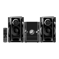
Identification and function of buttons on the main unit.

Remote Control Operation

Identification and function of buttons on the remote control.

Media Compatibility

Information regarding compatible media formats like CD and MP3.

Diagnostics and Modes

Cold-Start Procedure

Procedure to initialize the unit to shipping mode or perform a cold start.

Doctor Mode Tables

Details of diagnostic modes and their operations.

Reliability Test Mode

Process flow chart for the CD mechanism unit aging test.

Self-Diagnostic Mode

Entering and exiting service modes for diagnostics and error checks.

Self-Diagnostic Error Code Tables

Tables listing error codes for power supply and mechanism abnormalities.

Troubleshooting and Service Aids

F61/F76 Error Troubleshooting Guide

Procedures for diagnosing and resolving F61/F76 errors.

Part Location Diagrams

Visual identification of key components on specific PCBs.

D-Amp IC Operation and Control

Explanation of the D-Amp IC's operational logic and control signals.

Service Tools and Fixtures

Required Service Tools

List of specialized tools and equipment required for servicing.

Disassembly and Assembly Instructions

Disassembly Flow Chart

Diagram illustrating the sequence of disassembly steps for various unit components.

Component and PCB Locations

Visual guide showing the placement of major internal components and PCBs.

Cabinet and Panel Disassembly

Procedures for removing the top cabinet, tuner PCB, front panel, and panel PCB.

Internal PCB Disassembly

Procedures for removing remote sensor, CD open button, Jupiter, and music port/headphone PCBs.

Main PCB and Component Replacement

Steps to remove Main PCB and replace key components.

SMPS PCB Disassembly and Replacement

Procedures for disassembling SMPS PCB and replacing its components.

Mechanism and Rear Panel Disassembly

Procedures for removing the CD Mechanism Unit and Rear Panel.

Replacement of Traverse Unit

Disassembling Procedures

Step-by-step instructions for removing the traverse unit.

Assembling Procedure

Instructions for correctly assembling the traverse unit.

Service Position

Main PCB Checking and Repairing

Procedures for checking and repairing the Main PCB.

D-Amp PCB Checking and Repairing

Procedures for checking and repairing the D-Amp PCB.

Panel PCB Checking and Repairing

Procedures for checking and repairing the Panel PCB.

Jupiter PCB Checking and Repairing

Procedures for checking and repairing the Jupiter PCB.

SMPS PCB Checking and Repairing

Procedures for checking and repairing the SMPS PCB.

Voltage & Waveform Chart

CD SERVO P.C.B. Voltages

Voltage values for various reference points on the CD Servo PCB.

Main P.C.B. Voltages

Voltage values for specific points on the Main PCB.

Jupiter P.C.B. Voltages

Voltage values for the Jupiter PCB.

Panel P.C.B. Voltages

Voltage values for the Panel PCB.

SMPS P.C.B. Voltages

Voltage values for the SMPS PCB.

Tuner P.C.B. Voltages

Voltage values for the Tuner PCB.

Waveform Table

Illustration of ICs, Transistors, and Diodes

Simplified Block Diagrams

Overall Simplified Block Diagram

High-level block diagram showing main functional units and their interconnections.

D-Amp Block Diagram

Detailed block diagram of the D-Amp section, showing power and signal flow.

Block Diagrams

Servo/System Control Block Diagram

Block diagram illustrating the Servo and System Control circuitry.

IC Terminal Chart (Servo/System Control)

Terminal functions for key ICs involved in servo and system control.

Audio Block Diagram

Block diagram detailing the audio signal paths and processing.

Power Amplifier Block Diagram

Block diagram of the power amplifier section, showing signal flow to speakers.

Power Supply Block Diagram

Block diagram of the power supply unit and its various voltage outputs.

Wiring Diagram

Schematic Diagram Notes

Schematic Diagrams

CD Servo Circuit Schematic

Detailed schematic of the CD Servo circuit.

Main Circuit Schematics

Schematic diagrams of the main circuit board.

Jupiter Circuit Schematic

Schematic diagram of the Jupiter circuit.

Panel Circuit Schematic

Schematic diagram of the Panel circuit.

CD Open Button, Remote Sensor, Tuner, Music Port/Headphone Circuit Schematics

Schematics for CD Open Button, Remote Sensor, Tuner, and Music Port/Headphone circuits.

D-Amp Circuit Schematic

Schematic diagram of the D-Amp circuit.

SMPS Circuit Schematic

Schematic diagram of the SMPS circuit.

Voltage Selector Circuit Schematic (For PH Only)

Schematic of the voltage selector circuit (for PH models).

Printed Circuit Board Layouts

CD Servo & Voltage Selector PCB Layout

Layout of the CD Servo and Voltage Selector PCBs.

Main PCB Layout

Layout of the Main PCB.

Jupiter PCB Layout

Layout of the Jupiter PCB.

Panel PCB Layout

Layout of the Panel PCB.

Multiple PCB Layouts

Layouts for CD Open Button, Remote Sensor, Tuner, Music Port/Headphone, D-Amp PCBs.

SMPS PCB Layout (For PH Only)

Layout of the SMPS PCB for PH models.

SMPS PCB Layout (For PN Only)

Layout of the SMPS PCB for PN models.

Terminal Functions of ICs

IC2003 Micro-Processor Terminal Functions

Terminal functions for the Micro-Processor IC (IC2003).

IC6901 FL Driver Terminal Functions

Terminal functions for the FL Driver IC (IC6901).

Exploded View and Replacement Parts List

Exploded View of Mechanical Parts

Exploded view showing mechanical part locations and their replacement list.

Cabinet Parts Location

Exploded view showing the location of cabinet parts.

Packaging Diagram

Diagram illustrating the packaging of the product and accessories.

Mechanical Replacement Part List

Detailed list of mechanical replacement parts with their part numbers and descriptions.

Electrical Replacement Part List

List of electrical replacement components, including ICs, transistors, and diodes.

Related product manuals