EasyManua.ls Logo

Panasonic SA-BTT350P User Manual

Panasonic SA-BTT350P
149 pages
To Next Page IconTo Next Page
Page #1 background imageLoading...
Page #1 background image
© Panasonic Corporation 2010. All rights reserved.
Unauthorized copying and distribution is a violation
of law.
PSG1007003CE
A6
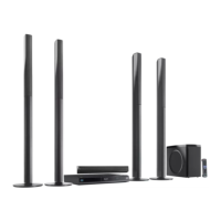
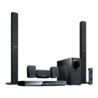
Blu-ray Disc Home Theater Sound System
Model No. SA-BTT350P
SA-BTT750P
Vol.1
Product Color: (K)...Black Type
TABLE OF CONTENTS
PAGE PAGE
1 Safety Precautions----------------------------------------------- 3
1.1. GENERAL GUIDELINES-------------------------------- 3
1.2. Before Repair and Adjustment ------------------------- 3
1.3. Protection Circuitry ----------------------------------------4
1.4. Safety Parts Information----------------------------------5
2Warning--------------------------------------------------------------6
Notes: Please refer to the original service manual for:
• Speaker system SB-BTT350P-K (For SA-BTT350P-K), Order No: PSG1007005CE.
• Speaker system SB-BTT750P-K (For SA-BTT750P-K), Order No: PSG1007006CE.
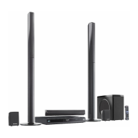
Table of Contents

Questions and Answers:

Panasonic SA-BTT350P Specifications

General IconGeneral
BrandPanasonic
ModelSA-BTT350P
CategoryHome Theater System
LanguageEnglish

Summary

Safety Precautions and Guidelines

General Guidelines and Leakage Current Checks

Essential safety rules, cold/hot leakage current checks for safe operation.

Before Repair and Adjustment Precautions

Precautions and steps to take before performing repairs or adjustments.

Warning and Electrostatic Discharge (ESD) Prevention

ESD Prevention Techniques

Techniques to prevent damage to sensitive electronic components from static electricity.

BD Drive Precautions

Specific safety considerations for handling the Blu-ray disc drive unit.

Service Navigation and Procedures

Service Information Overview

Overview of the service manual's content and ordering parts.

Firmware Update Procedures and Part Replacement Cautions

Instructions for firmware updates and cautions for replacing parts.

Specifications

General, Amplifier, and Laser Specs

Technical data for general, amplifier, and laser components.

Location of Controls and Components

Remote Control Key Operations

Explanation of functions for each button on the remote control.

Main Unit Key Button Operations

Details on the buttons and functions located on the main unit.

Broadband Network Connection Guide

Guide for connecting the unit to a network for internet services.

Network Easy Setting Procedures

Step-by-step process for configuring network connections easily.

Firmware Update Process

Instructions on how to update the device's firmware for new features or fixes.

Speaker Connection Guide

Diagram and instructions for connecting the speaker system to the main unit.

Disc and Card Playability

Information on supported disc types and memory card formats for playback.

Supported File Extension Types

List of supported file formats for media playback.

Operating Instructions

Forced Disc Ejection Procedures

Procedures for ejecting a disc when the unit is not functioning normally.

Self-Diagnostic and Special Mode Setting

Special Mode Table 1: Service and Diagnosis Modes

Table detailing special modes for service and self-diagnosis functions.

Error Code Table

List of error codes displayed by the unit and their potential meanings.

Service Mode Operations

Guide to entering and utilizing the service mode for diagnostics and adjustments.

Troubleshooting Guide

Troubleshooting for F61 and F76 Errors

Specific troubleshooting steps for common error codes F61 and F76.

SMPS PCB Component Identification

Visual guide to key components on the SMPS (Switched-Mode Power Supply) PCB.

Disassembly and Assembly Instructions

Disassembly Flow Chart Overview

A flowchart outlining the sequence for disassembling unit components.

Main Components and PCB Locations

Diagram showing the placement of major internal components and PCBs.

Top Cabinet Disassembly

Step-by-step instructions for removing the top cabinet cover.

AC Inlet PCB and Wireless Adapter PCB Disassembly

Procedures for removing the AC inlet and wireless adapter PCBs.

Fan Unit, Rear Panel, and Front Panel Disassembly

Instructions for removing the fan, rear panel, and front panel assemblies.

FL PCB, Power Button PCB, and DVD Lid Unit Replacement

Steps for removing FL PCB, power button PCB, and replacing DVD lid unit.

Main PCB and Digital PCB Disassembly

Detailed steps for removing the main and digital printed circuit boards.

BD Drive Disassembly and Tray Replacement

Instructions for removing the BD drive and replacing the disc tray.

D-Amp PCB Disassembly and Digital Amplifier IC Replacement

Procedure for removing D-Amp PCB and replacing the digital amplifier IC.

Power PCB, SMPS PCB, and Regulator Diode Replacement

Procedures for removing Power/SMPS PCBs and replacing regulator diodes.

Service Position Procedures

Main PCB Side A Checking & Repair

Procedures for checking and repairing the main PCB's side A.

D-Amp PCB Checking & Repair

Guide for inspection and repair of the D-Amp PCB.

SMPS PCB Checking & Repair

Procedures for checking and repairing the SMPS PCB.

Voltage and Waveform Charts

Main PCB Voltage Readings (1/5)

Voltage readings for various points on the Main PCB, part 1 of 5.

Waveform Table (1/2)

Visual representations and measurements of signal waveforms, part 1 of 2.

Block Diagrams

Simplified System Block Diagram

High-level overview of the system's functional blocks and their interconnections.

System Control Block Diagram

Detailed block diagram illustrating the system's control logic and signal flow.

Audio & Video Block Diagram

Block diagram showing the audio and video signal processing paths.

Power Supply (Main Section) Block Diagram

Block diagram detailing the main power supply circuits and their distribution.

Schematic Diagrams

Schematic Diagram Notes and Conventions

Explanations of symbols, conventions, and safety precautions used in diagrams.

Main Circuit Schematic

Detailed schematic diagram of the main circuit board and its components.

D-Amp Circuit Schematic

Detailed schematic diagram of the digital amplifier circuit.

SMPS Circuit Schematic

Detailed schematic diagram of the switched-mode power supply circuit.

Power, Button & AC Inlet Circuit Schematic

Schematic diagram for power supply, button controls, and AC input circuitry.

iPod & Wireless Adapter Circuit Schematic

Schematic diagrams detailing the iPod interface and wireless adapter connections.

FL Circuit Schematic

Schematic diagram for the front panel fluorescent display and its driver circuit.

Printed Circuit Board Layouts

Main PCB Layout (Side A)

Top-down view showing component placement on the Main PCB (Side A).

D-Amp PCB Layouts (Side A & B)

Visual layout of components on the D-Amp PCB, showing both sides.

SMPS PCB Layout

Component layout diagram for the SMPS PCB, indicating placement.

Power, Power Button, AC Inlet & iPod PCB Layouts

Component layouts for the Power, Power Button, AC Inlet, and iPod PCBs.

Wireless Adapter & FL PCB Layouts

Component layout diagrams for the Wireless Adapter and FL PCBs.

Terminal Function of ICs

IC FL Driver Terminal Functions

Detailed pinout and function description for the IC FL Driver IC6001.

Parts Lists and Exploded Views

Exploded View and Mechanical Parts List

Visual exploded view of unit parts with a list of mechanical replacement components.

Mechanical Replacement Parts List

Comprehensive list of mechanical replacement parts with part numbers and quantities.

Electrical Replacement Parts List (ICs)

List of integrated circuits (ICs) with part numbers and quantities.

Electrical Replacement Parts List (Resistors)

Comprehensive list of resistors with their values and part numbers.

Electrical Replacement Parts List (Capacitors)

List of capacitors with part numbers and values.

Related product manuals