EasyManua.ls Logo

Panasonic SA-BTT775GA User Manual

Panasonic SA-BTT775GA
173 pages
To Next Page IconTo Next Page
Page #1 background imageLoading...
Page #1 background image
© Panasonic Corporation 2011. All rights reserved.
Unauthorized copying and distribution is a violation
of law.
PSG1104020CE
Blu-ray Disc
TM
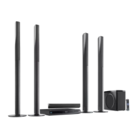
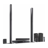
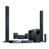
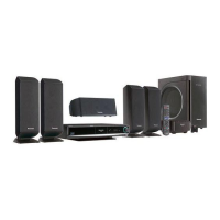
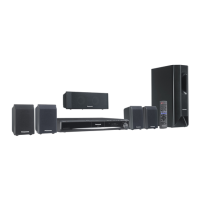
Home Theater Sound System
Model No. SA-BTT775GA
SA-BTT775PU
Vol.1
Product Color: (K)...Black Type
TABLE OF CONTENTS
PAGE PAGE
1 Safety Precautions----------------------------------------------- 3
1.1. GENERAL GUIDELINES-------------------------------- 3
1.2. Before Use -------------------------------------------------- 3
1.3. Before Repair and Adjustment ------------------------- 3
1.4. Protection Circuitry---------------------------------------- 4
1.5. Safety Parts Information --------------------------------- 5
2 Warning-------------------------------------------------------------- 6
2.1. Prevention of Electrostatic Discharge (ESD)
to Electrostatic Sensitive (ES) Devices---------------6
2.2. Precaution of Laser Diode -------------------------------7
2.3. Service caution based on Legal restrictions --------8
2.4. Handling Precaution for Traverse Unit----------------8
3 Service Navigation --------------------------------------------- 10
3.1. Service Information-------------------------------------- 10
Notes: Please refer to the original service manual for:
• Speaker system SB-BTT775EBK, Order No: PSG1103006CE

Table of Contents

Questions and Answers:

Panasonic SA-BTT775GA Specifications

General IconGeneral
TypeHome Theater System
Channels5.1
Total Power Output1000W
Blu-ray PlaybackYes
3D PlaybackYes
HDMI Output1
USB PlaybackYes
Smart FeaturesYes
Wi-FiYes
EthernetYes
Optical Input1
Blu-ray PlayerYes
BluetoothYes
FM TunerYes
Audio Formats SupportedDolby Digital, Dolby TrueHD, DTS-HD Master Audio

Summary

Safety Precautions

General Guidelines

General safety instructions for servicing and handling the equipment.

Leakage Current Cold Check

Procedure for checking leakage current by measuring resistance between AC plug and cabinet.

Leakage Current Hot Check

Procedure for measuring voltage across a resistor for hot leakage current.

Before Use

Instructions for setting the voltage selector before using the unit.

Before Repair and Adjustment

Precautions before performing repairs, including capacitor discharge and gradual power restoration.

Protection Circuitry

Explanation of protection circuitry and its function to prevent damage from shorts or low impedance speakers.

Safety Parts Information

List of critical safety parts marked with () in diagrams, requiring manufacturer-specified replacements.

Warning

Prevention of Electrostatic Discharge (ESD) to Electrostatic Sensitive (ES) Devices

Techniques to reduce damage from static discharge to ES devices during servicing.

Precaution of Laser Diode

Cautions regarding the laser diode, invisible radiation, and handling precautions.

Service caution based on Legal restrictions

Cautions regarding lead-free solder use and handling for environmental conservation.

Handling Precaution for Traverse Unit

Special care required when handling the optical pickup unit to avoid ESD damage.

Cautions to Be Taken in Handling the Optical Pickup Unit

Specific cautions for handling the optical pickup unit to avoid ESD damage.

Grounding for electrostatic breakdown prevention

Methods for grounding to prevent electrostatic breakdown during servicing.

Service Navigation

Service Information

Information for service personnel to understand and service the model.

Combination of Multiple Pressing on the Remote Control

Using multiple button presses on the remote for operations like initialization.

Entering Special Modes with Combination of Multiple Pressing on the Remote Control

How to enter special modes using combinations of remote control button presses.

Disclosure mode (Combination of multiple pressing: [OK] [BLUE] [YELLOW])

Enter disclosure mode by pressing OK, BLUE, YELLOW on remote for 5 seconds.

Nondisclosure mode 1 (Combination of multiple pressing: [6] [7] [Yellow])

Enter nondisclosure mode 1 by pressing 6, 7, Yellow on remote for 5 seconds.

Nondisclosure mode 2 (Combination of multiple pressing: [5] [9] [Red])

Enter nondisclosure mode 2 by pressing 5, 9, Red on remote for 5 seconds.

Caution for Replacing Parts

Cautions and procedures related to replacing parts, including firmware updates.

Firmware updates

Instructions on how to update the unit's firmware via internet or CD-ROM.

Items that should be done after replacing parts

List of essential checks and actions after replacing parts.

Standard Inspection Specifications after Making Repairs

Checklist for verifying normal operation after repairs.

Specifications

Others (Licenses)

List of software licenses and trademarks used in the product.

Location of Controls and Components

Remote Control Key Button Operations

Explanation of the functions of each button on the remote control.

Main Unit Key Button Operations

Description of controls and connections on the main unit's front and rear panels.

Speaker Connection

Diagram and instructions for connecting the speaker system to the main unit.

Connection to a Broadband Network

How to connect the unit to a broadband network for updates and online services.

Network Easy Setting

Step-by-step guide for setting up network connections, including wired and wireless options.

Firmware Updates

Procedures for updating the unit's firmware to improve performance or add features.

Enjoying BD-LIVE or picture in picture in BD-Video

How to use BD-LIVE features and picture-in-picture playback in BD-Video.

Regarding Divx

Information about DivX video format and registration for DivX Video-on-Demand.

Enjoying 3D Video

Instructions for connecting and configuring the unit for 3D video playback.

Using the iPod/iPhone

How to connect and use an iPod or iPhone with the unit.

iPod /iPhone Connection

Steps for physically connecting an iPod or iPhone to the unit's dock.

iPod /iPhone Playback

How to select and play music or photos from a connected iPod or iPhone.

Enjoying VIERA CAST

Accessing internet services and content through VIERA CAST on the home media system.

Playing Back Contents on the DLNA Server (DLNA)

How to play back media content stored on a DLNA-certified server.

Playable disc/Cards

List of supported disc formats (BD, DVD, CD) and card types (SD, USB) and their content formats.

File Extension Type Support (MP3/JPEG/DivX/MKV)

Supported file formats and their corresponding file extensions for media playback.

Operating Instructions

Removing of disc during abnormality

Procedures to remove a disc when the unit is unresponsive or the tray cannot be ejected normally.

Self-Diagnostic and Special Mode Setting

Special Mode Setting

Overview and table of special modes available for unit settings and diagnostics.

Self-Diagnostic Function - Error Code

Table of error codes, diagnosis contents, and corresponding FL display messages for self-diagnosis.

Service Mode

Instructions on how to enter and navigate the service mode for diagnostic purposes.

Troubleshooting Guide

Troubleshooting Guide for F61 and/or F76

Guide to diagnose and resolve F61 and F76 errors related to power and output voltage issues.

Service Fixture & Tools

Service Tools and Equipment

List of necessary service tools and equipment for performing repairs and maintenance.

Disassembly and Assembly Instructions

Disassembly Flow Chart

Flowchart illustrating the order of disassembly for various unit components.

Main Components and P.C.B. Locations

Diagram showing the locations of major components and printed circuit boards within the unit.

Disassembly of Top Cabinet

Step-by-step instructions for removing the top cabinet of the unit.

Disassembly of Wireless Adapter P.C.B.

Procedures for disassembling the wireless adapter printed circuit board.

Disassembly of Rear Panel

Instructions for removing the rear panel of the unit.

Disassembly of Voltage Selector P.C.B.

Steps for removing the voltage selector printed circuit board.

Disassembly of Fan

How to remove the cooling fan from the unit.

Disassembly of Front Panel Assembly

Procedures for disassembling the front panel assembly.

Disassembly of Panel P.C.B.

Steps for removing the panel printed circuit board.

Disassembly of Operation Button P.C.B.

Instructions for removing the operation button printed circuit board.

Disassembly of Power Button P.C.B.

Procedures for removing the power button printed circuit board.

Disassembly of iPod Cradle Assembly

Steps for disassembling the iPod cradle assembly.

Disassembly of iPod P.C.B.

Instructions for removing the iPod printed circuit board.

Replacement of Front Lid Assembly

Detailed steps for replacing the front lid assembly of the unit.

Disassembly of BD Mechanism Unit (BRS1P)

Step-by-step guide to disassemble the BD mechanism unit for repair or replacement.

Disassembly of Dust Cover

Instructions for removing the dust cover of the BD mechanism unit.

Replacement of Tray

Procedures for replacing the disc tray of the BD mechanism unit.

Replacement of BD Traverse Unit

Steps for replacing the BD traverse unit, including disassembly and assembly.

Checking point after replacement of Traverse Unit

Points to check after replacing the traverse unit, ensuring proper gap and damper function.

Replacement of Slide Cam

How to replace the slide cam mechanism in the BD unit, including disassembly and assembly.

Replacement of Belt

Procedures for replacing the drive belt in the BD mechanism unit.

Replacement of Pulley Gear

Steps for replacing the pulley gear in the BD mechanism unit.

Replacement of Driver Gear

How to replace the driver gear in the BD mechanism unit.

Replacement of Loading P.C.B.

Procedures for replacing the loading printed circuit board in the BD mechanism unit.

Replacement of Loading Motor

Steps for replacing the loading motor in the BD mechanism unit.

Disassembly of AC Inlet P.C.B.

Procedures for removing the AC inlet printed circuit board from the unit.

Disassembly of D-Amp P.C.B.

Steps for removing the D-Amp (Digital Amplifier) printed circuit board.

Replacement of Digital Amplifier IC (IC5100/IC5200/IC5300)

Detailed procedure for replacing the digital amplifier ICs on the D-Amp PCB.

Disassembly of Digital P.C.B.

Steps for removing the main digital printed circuit board.

Disassembly of AV P.C.B.

Procedures for removing the AV (Audio/Video) printed circuit board.

Disassembly of SMPS P.C.B.

Steps for removing the SMPS (Switch Mode Power Supply) printed circuit board.

Replacement of Switching Regulator IC (IC5701)

Procedure for replacing the switching regulator IC on the SMPS PCB.

Replacement of Rectifier Diode (D5702)

Procedure for replacing the rectifier diode on the SMPS PCB.

Replacement of Thermal Diode (D5802)

Procedure for replacing the thermal diode on the SMPS PCB.

Replacement of Regulator Diode (D5803)

Procedure for replacing the regulator diode on the SMPS PCB.

Service Position

Checking & Repairing of Digital P.C.B.

Procedures for checking and repairing the digital PCB, including side B and side A.

Checking & Repairing of Digital P.C.B. (Side B)

Detailed steps for checking and repairing the digital PCB, side B.

Checking & Repairing of Digital P.C.B. (Side A)

Steps for checking and repairing the digital PCB, side A.

Checking & Repairing D-Amp P.C.B.

Procedures for checking and repairing the D-Amp PCB, including side B and side A.

Checking & Repairing of D-Amp P.C.B. (Side B)

Procedures for checking and repairing the D-Amp PCB, side B.

Checking & Repairing of D-Amp P.C.B. (Side A)

Steps for checking and repairing the D-Amp PCB, side A.

Checking & Repairing SMPS P.C.B.

Procedures for checking and repairing the SMPS (Switch Mode Power Supply) PCB.

Checking & Repairing Panel P.C.B.

Steps for checking and repairing the panel PCB.

Checking & Repairing of AV P.C.B.

Procedures for checking and repairing the AV (Audio/Video) PCB.

Voltage & Waveform Chart

Digital P.C.B. (1/3)

Voltage values for the digital PCB, measured at various points.

Digital P.C.B. (2/3)

Voltage values for the digital PCB, continuing from the previous section.

Digital P.C.B. (3/3)

Final set of voltage values for the digital PCB.

AV P.C.B.

Voltage values measured on the AV (Audio/Video) PCB.

Panel P.C.B.

Voltage values measured on the Panel PCB.

D-Amp P.C.B. (1/2)

Voltage values for the D-Amp PCB, starting the first part.

D-Amp P.C.B. (2/2)

Voltage values for the D-Amp PCB, continuing the second part.

SMPS P.C.B.

Voltage values measured on the SMPS (Switch Mode Power Supply) PCB.

Waveform Table (1/2)

Visual representations of waveforms at various test points on the digital PCB.

Waveform Table (2/2)

Visual representations of waveforms at various test points, continuing the table.

Illustration of ICs, Transistor and Diode

Simplified Block Diagram

Block Diagram

System Control

Block diagram illustrating the system control flow and major control components.

Audio & Video

Block diagram detailing the audio and video signal paths and processing units.

Power Supply(Main Section)

Block diagram of the main power supply section, showing its internal components and connections.

Wiring Connection Diagram

Schematic Diagram

Schematic Diagram Notes

Notes and symbols used in the schematic diagrams, including safety warnings and component identification.

Digital(Micon/Power) Circuit

Schematic diagram of the digital and power control circuits.

AV Circuit

Schematic diagram of the audio and video processing circuits.

D-Amp Circuit

Schematic diagram of the digital amplifier (D-Amp) circuit.

Panel Circuit

Schematic diagram of the front panel interface and display circuits.

Power Button, Operation Button & iPod Circuit

Schematic diagram for power button, operation button, and iPod interface circuits.

SMPS Circuit

Schematic diagram of the Switch Mode Power Supply (SMPS) circuit.

AC Inlet, Wireless Adapter & Voltage Selector Circuit

Schematic diagrams for AC inlet, wireless adapter, and voltage selector circuits.

Printed Circuit Board

Digital P.C.B.

Top and bottom views of the digital PCB, showing component placement.

AV, Panel, Power Button, Operation Button & iPod P.C.B.

Views of the AV, Panel, Power Button, Operation Button, and iPod PCBs, showing component placement.

D-Amp P.C.B.

Top and bottom views of the D-Amp PCB, showing component placement.

SMPS, AC Inlet, Wireless Adapter & Voltage Selector P.C.B.

Views of SMPS, AC Inlet, Wireless Adapter, and Voltage Selector PCBs, showing component placement.

Terminal Function of ICs

IC6001(C0HBB0000057): IC FL Driver

Detailed pinout and function description for the IC FL Driver (IC6001).

Exploded View and Replacement Parts List

Exploded View and Mechanical replacement Part List

Exploded views of the unit and a list of mechanical replacement parts with reference numbers.

Cabinet Parts Location

Diagram showing the location of cabinet parts and assemblies.

BD Mechanism

Exploded view of the BD mechanism unit, showing its internal components.

Packaging

Diagram illustrating the packaging of the unit and its accessories for shipping.

Mechanical Replacement Part List

Comprehensive list of mechanical replacement parts with part numbers, descriptions, and quantities.

Electrical Replacement Parts List

List of electrical replacement parts including PCBs, ICs, transistors, diodes, and other components.

Related product manuals