EasyManua.ls Logo

Panasonic SB-HS650P - User Manual

Panasonic SB-HS650P
11 pages
Print Icon
To Next Page IconTo Next Page
Loading...
Type 1 way, 1 speaker system (Bass reflex)
Speaker unit(s) Impedance 3
Full range 6.5 cm (2-1/2”) cone type
Input power (IEC) 125* W (Max)
Output sound pressure 80 dB/W (1.0 m)
Frequency range 95 Hz to 25 kHz (-16 dB)
120 Hz to 22 kHz (-10 dB)
Dimensions (W x H x D) 92 x 142 x 95 mm
1 System Combination
2
1.1. System Breakdown
2
1.2. Packaging Information
2
2 Assembling and Disassembling
3
2.1. Disassembly flow chart
3
2.2. Disassembly of Rear cabinet assembly
4
© 2007 Matsushita Electric Industrial Co. Ltd.. All
rights reserved. Unauthorized copying and
distribution is a violation of law.
SB-HS650P
Colour
(S)... Silver Type
(3-5/8” x 5-19/32” x 3-3/4”)
Mass 0.6 kg (1.32lb.)
Notes :
1. Specifications are subject to change without notice.
Mass and dimensions are approximate.
2. Total harmonic distortion is measured by the digital spectrum
analyzer.
* : Rating with low-cut filter equipped amplifier.
2.3. Disassembly of Woofer
5
3 Connection of the Speaker Cables
6
4 Connection of the Wiring Diagram
9
5 Exploded view
10
5.1. Cabinet Parts Location
10
6 Replacement Parts List
11
Speaker System
Specification
CONTENTS
Page Page
ORDER NO. MD0702015CE
A6
Question and Answer IconNeed help?

Do you have a question about the Panasonic SB-HS650P and is the answer not in the manual?

Overview

This document is a service manual for the Panasonic SB-HS650P speaker system. It provides detailed information for experienced repair technicians, covering specifications, assembly, disassembly, connection, and replacement parts.

Function Description

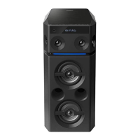
The SB-HS650P is a 1-way, 1-speaker bass reflex speaker system designed to be part of a larger home theater setup. It functions as a surround speaker within the Panasonic SC-PT650P/PC-S or SA-PT650P/PC-S systems. The speaker is designed to reproduce audio signals, contributing to the overall sound field of the system. It is specifically intended for use with the supplied main unit and other speakers within the specified system combination.

Important Technical Specifications

  • Type: 1 way, 1 speaker system (Bass reflex)
  • Speaker Unit: 6.5 cm (2-1/2") cone type, full range
  • Impedance: 3 Ω
  • Input Power (IEC): 125 W (Max) - Note: Rating with low-cut filter equipped amplifier.
  • Output Sound Pressure: 80 dB/W (1.0 m)
  • Frequency Range:
    • 95 Hz to 25 kHz (-16 dB)
    • 120 Hz to 22 kHz (-10 dB)
  • Dimensions (W x H x D): 92 x 142 x 95 mm (3-5/8" x 5-19/32" x 3-3/4")
  • Mass: 0.6 kg (1.32 lb.)
  • Color: (S)... Silver Type
  • Total Harmonic Distortion: Measured by a digital spectrum analyzer.

The speaker system is part of the SB-PT650P-S speaker package, which includes:

  • SB-HF650P-S (x 2) - Front speakers
  • SB-HS650P-S (x 2) - Surround speakers
  • SB-HC750P-S (x 1) - Center speaker
  • SB-HW750P-S (x 1) - Subwoofer

Usage Features

The manual emphasizes proper setup and connection for optimal performance and to prevent damage.

Speaker Placement:

  • Speakers should be placed on flat, secure bases.
  • Avoid placing speakers too close to floors, walls, and corners, as this can result in excessive bass.
  • Walls and windows should be covered with thick curtains for better sound.
  • Maintain at least 10 mm (13/32") clearance from the system for proper ventilation.
  • For surround speakers (SB-HS650P-S), they should be placed at approximately the same distance from the seating position as the front and center speakers.
  • Left and right surround speakers are interchangeable, and there is no specific left or right channel orientation required.
  • The recommended angle for surround speakers relative to the listening position is 120°.

Speaker Cable Connection:

  • Speaker cables must be connected before the AC power supply cord.
  • The load impedance of any speaker used with this unit must be 3 Ω.
  • Ensure correct polarity: positive (white) wires to positive (+) terminals and negative (blue) wires to negative (-) terminals.
  • Twist and pull off the vinyl tip of the speaker cords. If no vinyl tips, connect bare ends directly to terminals, ensuring wires are not unraveled.
  • Insert the wire into the rear panel of the unit and close the lever.
  • Caution: Do not short-circuit or reverse the polarity of speaker wires, as this can damage the speakers. Speaker cable stickers are included to facilitate correct connection.

General Speaker Use Notes:

  • Only supplied speakers should be used; using other speakers can damage the unit and negatively affect sound quality.
  • Avoid playing sound at high levels for extended periods to prevent damage and shorten speaker life.
  • Reduce volume when:
    • Playing distorted sound.
    • Speakers are reverberating due to a record player, FM broadcast noise, or continuous signals from an oscillator, test disc, or electronic instrument.
    • Adjusting sound quality.
    • Turning the unit on or off.
  • Irregular Coloring on Television: Front and center speakers can affect television picture quality. If irregular coloring occurs, turn the television off for about 30 minutes to allow the demagnetizing function to correct the problem. If it persists, move the speakers further away from the television.
  • Safety Warning: The main unit and supplied speakers are to be used only as indicated in this setup. Failure to do so may lead to damage to the amplifier and/or speakers, and may result in fire. Consult a qualified service person if damage occurs or if performance changes. Do not attempt to attach these speakers to walls using methods other than those described in this manual.
  • Handling: Do not touch the front netted area of the speakers; hold them by the sides.

Maintenance Features

The manual is primarily for service and maintenance by experienced technicians.

Assembly and Disassembly Procedures:

  • The manual provides a detailed disassembly flow chart for internal inspection and component replacement.
  • Disassembly of Rear Cabinet Assembly:
    1. Remove 4 screws (a).
    2. Upset the speaker unit.
    3. Insert a steel rule at the bottom corner of the rear cabinet assembly.
    4. Apply light force to push out the front panel. Caution: Do not exert strong force to avoid damaging the rear cabinet assembly.
    5. Detach the blue (-) and white (+) wires from the woofer.
  • Disassembly of Woofer:
    1. Follow steps 1 to 5 for rear cabinet disassembly.
    2. Remove 4 screws (a) securing the woofer.
  • Reassembly: To assemble the unit, reverse the disassembly steps. Special reassembly procedures are described only when required.
  • Caution: Some chassis components may have sharp edges. Be careful when disassembling and servicing. Original screws should be used for reassembly.

Replacement Parts List:

  • The manual includes a comprehensive list of replacement parts for the cabinet, chassis, and speaker.
  • Important Safety Notice: When replacing components, only manufacturer-specified parts shown in the parts list should be used.
  • Parts marked with "[M]" in the Remarks column are supplied by PAVCSG.
  • Key Replacement Parts:
    • RYFX0186-K: FRONT PANEL ASS'Y
    • RYKX0347-S: REAR CABINET ASS'Y
    • RGNX0460-S2: SPEC LABEL
    • RKA0072-KJ: LEG RUBBER
    • XTB3+10GFJ: SCREW
    • EAS65P129B: SPEAKER (SP1)

The document serves as a critical resource for ensuring the proper functioning and longevity of the SB-HS650P speaker system through correct installation, usage, and professional servicing.

Panasonic SB-HS650P Specifications

General IconGeneral
BrandPanasonic
ModelSB-HS650P
CategorySpeakers
LanguageEnglish

Related product manuals